
")
1. What is Light?
Light is a form of energy that enables us to see objects. It travels in straight lines as a wave.
2. Reflection of Light
This is the phenomenon where light bounces back when it hits a smooth, shiny surface like a mirror. The two main laws are:
3. Regular and Diffused Reflection
Regular Reflection: Happens from smooth surfaces (like a mirror), creating a clear image.
Diffused Reflection: Happens from rough surfaces (like paper), scattering light in all directions so no clear image is formed. This is why we can see non-shiny objects from any angle.
4. Human Eye
The eye works like a camera. Key parts include:
Cornea: The transparent front part.
Iris: The colored part that controls the pupil size.
Pupil: The opening that lets light in.
Lens: Focuses light onto the retina.
Retina: The screen at the back where an inverted image is formed, which the brain corrects.
5. Care of the Eyes
To protect our eyes, we should avoid reading in dim or very bright light, not look directly at the sun, and maintain a proper distance while reading or watching screens.
6. Braille System
This is a special reading and writing system for visually impaired people. It uses raised dots on paper that can be felt with fingertips, allowing them to read.
Test yourself
A. Objective Questions
1. Write true or false for each statement
(a) Water is optically denser than glass.
Ans: False.
(b) A ray of light when passes from glass to air, bends towards the normal.
Ans: False.
(c) The speed of light is more in glass than in water.
Ans: False.
(d) The depth of a pond when seen from above appears to be less.
Ans: True.
(e) Light travels at a lower speed in water than in air.
Ans: True.
(f) Light travels in the same straight line path while passing through different media.
Ans: False.
(g) The angle formed between the normal and the refracted ray is known as the angle of incidence.
Ans: False.
(h) At the point of incidence, a line drawn at right angles to the surface, separating the two media, is called the normal.
Ans:True.
(i) Image is formed by a mirror due to refraction of light.
Ans: False.
(j) Rays of light incident parallel to the principal axis pass through the focus after reflection from a concave mirror.
Ans:True.
(k) A convex mirror is used as a shaving mirror.
Ans: False.
(l) The focal length of a convex mirror is equal to its radius of curvature.
Ans: False.
(m) A concave mirror converges the light-rays, but a convex mirror diverges them.
Ans:True.
(n) A virtual image formed by a spherical mirror is always erect and situated behind the mirror.
Ans:True.
2. Fill in the blanks
(a) Water is optically denser than air.
(b) Air is optically rarer than glass.
(c) When a ray of light travels from water to air, it bends away from the normal.
(d) When a ray of light travels from air to glass, it bends towards the normal.
(e) When white light passes through a prism, it disperses
(f) The splitting of white light into its constituent colours is called dispersion.
(g) A concave mirror is obtained on silvering the outer surface of a part of a hollow glass sphere.
(h) Radius of curvature of a spherical mirror is two times its focal length.
(i) The angle of incidence for a ray of light passing through the centre of curvature of a spherical mirror is 0°
(j) A convex mirror always forms a virtual image.
(k) A concave mirror forms a virtual image for an object placed between pole and focus.
Ans:
(a) Water is optically denser than air.
(b) Air is optically rarer than glass.
(c) When a ray of light travels from water to air, it bends away from the normal.
(d) When a ray of light travels from air to glass, it bends towards the normal.
(e) When white light passes through a prism, it disperses
(f) The splitting of white light into its constituent colours is called dispersion.
(g) A concave mirror is obtained by silvering the outer surface of a part of a hollow glass sphere.
(h) The radius of curvature of a spherical mirror is two times its focal length.
(i) The angle of incidence for a ray of light passing through the centre of curvature of a spherical mirror is 0°
(j) A convex mirror always forms a virtual image.
(k) A concave mirror forms a virtual image for an object placed between pole and focus.
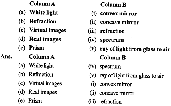
3. Match the following
4. Select the correct alternative
(a) The speed of light in air or vacuum is
- 3 × 10⁸ M s-1
- 2.25 × 10⁸ m s-1
- 332 ms-1
- 2.0 × 10⁸ ms-1
Ans: 3 × 10⁸ M s-1
(b) A ray of light moving from an optically rarer to a denser medium
- bends away from the normal
- bends towards the normal
- remains undeviated
- none of the above
Ans: bends towards the normal
(c) The angle between the normal and refracted ray is called
- angle of deviation
- angle of incidence
- angle of refraction
- angle of emergence.
Ans: angle of refraction
(d) The property of splitting of white light into its seven constituent colours is known as
- rectilinear propagation
- refraction
- reflection
- Dispersion
Ans: Dispersion
(e) The seven colours in the spectrum of sunlight in order, are represented as :
- VIBGYOR
- VIGYBOR
- BIVGYOR
- RYOBIVG
Ans:VIBGYOR
(f) A ray of light passing through centre of curvature of a spherical mirror, after reflection
- passes through the focus
- passes through the pole
- becomes parallel to the principal axis
- retraces its own path.
Ans: retraces its own path.
(g) If the radius of curvature of a concave mirror is 20 cm, its focal length is:
- 10 cm
- 20 cm
- 40 cm
- 80 cm
Ans: 10 cm
(h) The image formed by a convex mirror is
- erect and diminished
- erect and enlarged
- inverted and diminished
- inverted and enlarged.
Ans: erect and diminished
(i) The image formed by a concave mirror is of the same size as the object, if the object is placed
- at the focus
- between the pole and focus
- between the focus and centre of curvature
- at the centre of curvature.
Ans: at the centre of curvature.
(j) A convex mirror is used
- as a shaving mirror
- as a head mirror by a dentist
- as a rear view mirror by a driver
- as a reflector in torch.
Ans: as a head mirror by a dentist
(B) Short/Long Answer Questions
Question 1. State the speed of light in (a) air, (b) water, and (c) glass
Ans: (a) Speed of light in Air:Light travels through air at a speed very close to its speed in a vacuum. The difference is so small that for most practical purposes, we consider it to be about 299,700 kilometers per second or roughly 3.0 × 10⁸ m/s. The slight reduction is because air, while mostly empty space, still contains molecules that slow the light down a tiny bit.
(b) Speed of light in Water: Water is denser than air, so light slows down more significantly. In water, light travels at approximately 225,000 kilometers per second (or 2.25 × 10⁸ m/s). This is about 75% of its speed in a vacuum.
(c) Speed of light in Glass:Glass is optically denser than both air and water. Therefore, light slows down even more when passing through it. In typical glass, the speed of light is about 200,000 kilometers per second (or 2.0 × 10⁸ m/s). This is roughly two-thirds of its maximum speed.
Question 2. How does the speed of light determine the optical density of a medium ?
Ans: The speed of light in a medium determines its optical density.
Optical density indicates how much a medium can slow down light. It is quantitatively defined by the refractive index (n) of the medium.
The relationship is given by:
Refractive Index (n) = (Speed of light in vacuum, c) / (Speed of light in medium, v)
From this formula:
A higher refractive index (n) means light travels slower (v is smaller) in that medium. This signifies a higher optical density.
A lower refractive index (n) means light travels faster (v is larger) in that medium. This signifies a lower optical density.
Question 3. Which is optically denser : water or air ? Give reason.
Ans: Water is optically denser than air.
Reason:
Light travels slower in water than in air. Since the optical density of a medium is determined by how much it slows down light, water is optically denser.
Question 4. Out of air and glass, which is optically rarer ? Give reason.
Ans: Air is optically rarer than glass.
Reason:
A medium in which light travels faster is considered optically rarer. Since light travels faster in air than in glass, air is the optically rarer medium.
Question 5. What do you understand by refraction of light ?
Ans: Refraction of Light
Refraction is the bending of light when it passes from one transparent medium into another. This bending occurs because light changes speed as it moves between media of different densities, like from air into water or glass.A common example is a straw appearing bent in a glass of water.
Question 6. Describe an experiment to show that a light ray bends when it passes from one transparent medium into another transparent medium.
Ans:
Aim: To show that a light ray bends when it passes from one medium to another.
Apparatus: A rectangular glass slab, drawing board, white paper, pins, protractor, scale, pencil.
Procedure:
- Place the glass slab in the centre of the paper and draw its outline, ABCD. Remove the slab.
- Draw a normal (a perpendicular line) at point O on side AB.
- Draw an incident ray, MO, making a certain angle (angle of incidence).
- Stick two pins, P1 and P2, vertically on the incident ray line.
- Look through the opposite side (CD) of the slab and stick two more pins, P3 and P4, such that all four pins appear to be in a straight line.
- Remove the pins and the slab.
- Mark the positions of P3 and P4. Draw a line through these points back to the outline at point O’. This is the emergent ray.
- Join points O and O’. This line inside the slab is the refracted ray.
Observation: The incident ray (MO) and the emergent ray (O’N) are parallel, but the refracted ray (OO’) inside the glass slab is not in a straight line with the incident ray. It is bent at point O.
Conclusion: This bending of the light ray at the boundary between air and glass shows that light changes direction (refracts) when it passes from one transparent medium to another.
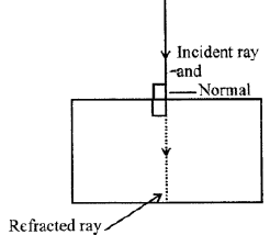
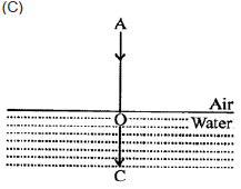
Question 7. Draw a ray diagram to show that the depth of a vessel containing water when seen from above, appears to be less than its real depth.
Ans: Ray Diagram Explanation:
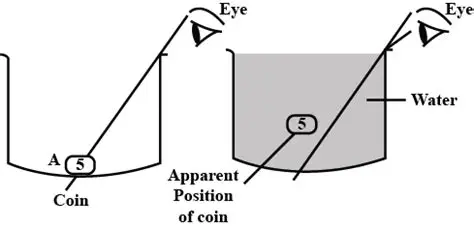
When viewed from above, the real depth of water appears to decrease due to refraction of light.
Steps to draw the ray diagram:
- Draw a water surface (interface between air and water).
- Mark point O at the bottom of the vessel (object point).
- From O, draw two rays traveling upwards:
- One incident normally (perpendicular to the surface) — it goes straight without bending.
- Another incident obliquely — it bends away from the normal as it enters air (rarer medium).
- Extend the refracted rays backwards (dotted lines). They meet at point I, above O.
- I is the virtual image of O, seen by the observer.
- The distance from the surface to I is the apparent depth, which is less than the real depth (O to surface).
Conclusion:
Because light rays bend at the water-air interface, the image of the bottom is shifted upward, making the vessel appear shallower than it actually is.
Question 8. Define the following terms : Incident ray, Refracted ray, Angle of incidence, Angle of refraction.
Ans:
Incident ray: The ray of light that travels from the source and falls on the surface separating two different media.
Refracted ray: The ray of light that bends and travels into the second medium after falling on the separating surface.
Angle of incidence: The angle formed between the incident ray and the normal (a perpendicular line) drawn at the point of incidence on the surface.
Angle of refraction: The angle formed between the refracted ray and the normal drawn at the point of incidence on the surface.
Question 9. A ray of light falls normally on a glass slab. What is the angle of incidence ?
Ans:
When a ray of light falls normally (perpendicularly) on a surface, the angle between the incident ray and the normal is 0°.
Therefore, the angle of incidence is 0°.
Question 10. A ray of light travels from a rarer medium to a denser medium. How will it bend ?
Ans:
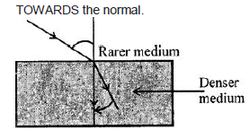
When a ray of light travels from a rarer medium (like air) into a denser medium (like glass or water), it bends towards the normal.
Explanation:
This happens because light slows down when it enters a denser medium. The change in speed causes the light ray to change direction. The bending of light as it passes from one transparent medium to another is known as refraction. The normal is an imaginary line drawn perpendicular to the surface at the point where the light ray hits. Since the light is slowing down in the denser medium, it bends toward this perpendicular (normal).
Question 11. A ray of light travels from a denser medium to a rarer medium. How will it bend ?
Ans:
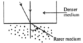
When a ray of light travels from a denser medium (like glass or water) into a rarer medium (like air), it bends away from the normal.
Reasoning:
This happens because light travels slower in a denser medium and faster in a rarer medium. As the light wavefront enters the rarer medium, one part of it speeds up first, causing the entire ray to change direction. Think of it like a car driving off-road: if the right-side wheels hit the pavement (a rarer, faster medium) first, the car will veer or “bend” to the left. Similarly, the light ray bends away from the imaginary line perpendicular to the surface (the normal) as it speeds up into the less dense material.
Question 12. The diagram given below in fig shows a ray of light AO falling on a surface separating two media. Draw the refracted ray in each, case.
Ans:
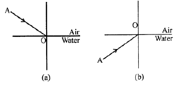
Case (a):
The ray AO passes from a rarer medium to a denser medium (e.g., air to glass).
The refracted ray bends towards the normal inside the second medium.
Case (b):
The ray AO passes from a denser medium to a rarer medium (e.g., glass to air).
The refracted ray bends away from the normal inside the second medium.
In both cases, the bending occurs at the point of incidence O on the surface.
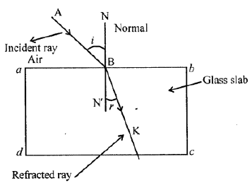
Question 13. Draw a diagram showing the refraction of a light ray from water to glass. Label on it the incident ray, the angle of incidence (/), and the angle of refraction R
Ans:
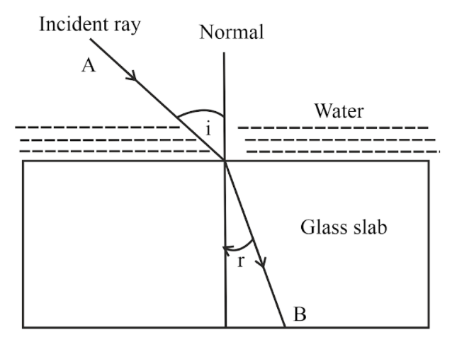
A light ray travels from water into glass. At the boundary, the ray bends towards the normal.
Labels:
Incident Ray: The incoming ray in the water.
Angle of Incidence (∠i): The angle between the incident ray and the normal.
Angle of Refraction (∠r): The angle between the refracted ray in the glass and the normal.
The refracted ray in the glass is closer to the normal than the incident ray, showing that glass is optically denser than water.
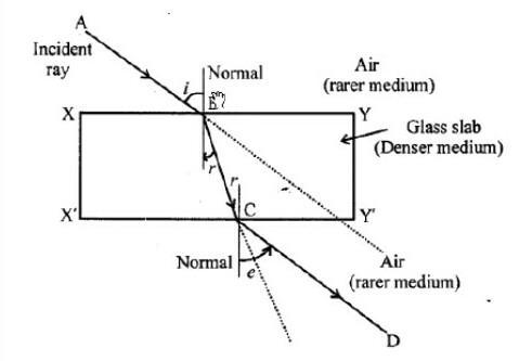
Question 14. The diagram in figure shows a ray of light AO falling on a rectangular glass slab PQRS. Complete the diagram till the ray of light emerges out of the slab. Label on the diagram the incident ray, the refracted ray and the emergent ray.
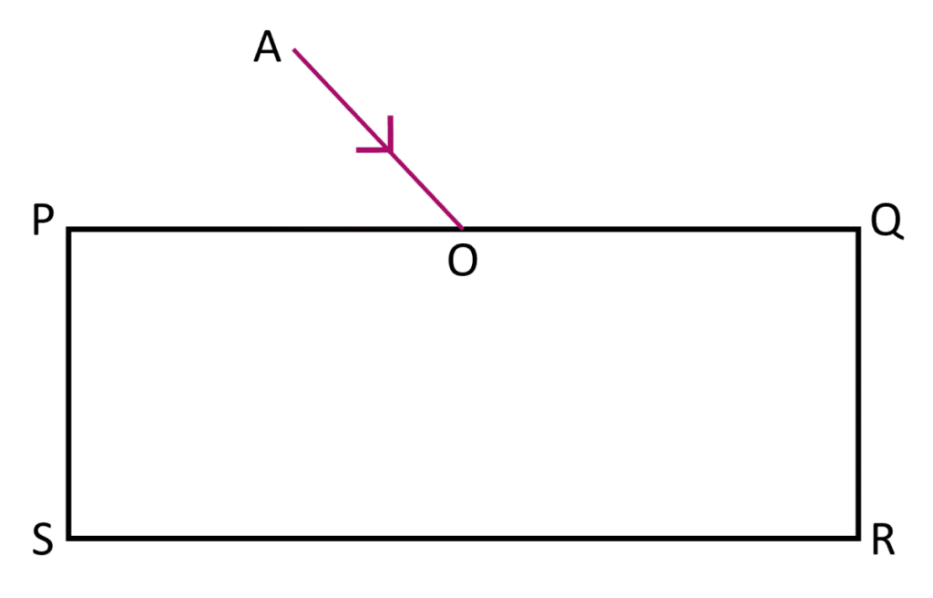
Ans:
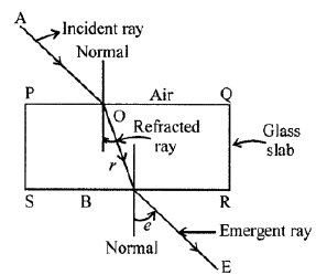
AO is the Incident Ray.
At point O on the air-glass interface, the ray bends towards the normal. OB is the Refracted Ray inside the slab.
At point B on the glass-air interface, the ray bends away from the normal. BC is the Emergent Ray.
Key Observation: The emergent ray (BC) is parallel to the original incident ray (AO) but is laterally displaced.
Question 15. Explain the following : (a) A coin placed at the bottom of a vessel appears to be raised when water is poured in the vessel. (b) A straight stick partly dipped in water obliquely, appears to be bent at the surface of water. (c) The sun is seen before the sunrise and after the sunset.
Ans:
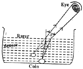
(a) Coin at the bottom of a vessel appears raised
This happens due to refraction of light. When water is poured into the vessel, light rays from the coin travel from water (denser medium) to air (rarer medium). They bend away from the normal as they enter the eye. The refracted rays appear to come from a point higher than the coin’s actual position, making it seem raised.
(b) Straight stick dipped in water looks bent
This is also due to refraction. The part of the stick in water is in a denser medium (water), while the part in air is in a rarer medium. Light from the underwater part bends away from the normal when it passes into the air, making the stick appear bent at the water surface.
(c) Sun seen before sunrise and after sunset
This occurs because of atmospheric refraction. The earth’s atmosphere bends sunlight towards the normal as it enters the denser layers near the surface. So, when the sun is actually slightly below the horizon, its light bends and reaches the observer. This makes the sun appear before actual sunrise and after actual sunset.
Question 16. What is mirage ? Give a reason for its formation ?
Ans:
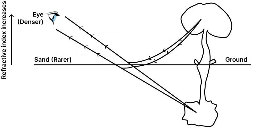
A mirage is an optical illusion where an inverted image of a distant object, often resembling water, appears on hot surfaces like a road.
It forms because the air near the hot ground is less dense than the cooler air above it. When light from the sky passes down towards the ground, it travels from denser to rarer air. This causes the light rays to refract continuously upwards. If the angle is steep enough, the light undergoes total internal reflection and bends upward towards an observer’s eyes. Our brain perceives this reflected light as coming from the ground, creating the water illusion.
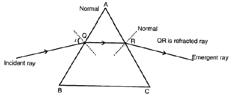
Question 17. What is a prism ? Draw a ray diagram to show7 the refraction of a light ray through a prism.
Ans:
It is typically made of glass or plastic and has a triangular cross-section.
Ray Diagram for Refraction Through a Prism:
A light ray (AB) traveling in air is incident on the first surface of the prism.
At point B, it bends towards the normal as it enters the denser glass medium (refraction).
Inside the prism, the ray (BC) travels in a straight line to the second surface.
At point C, it bends away from the normal as it exits into the less dense air medium (refraction again).
The emergent ray (CD) is deviated from its original path. The angle between the emergent and incident rays is called the angle of deviation.
The diagram shows the path of the ray bending first towards the base of the prism upon entry and then away from the base upon exit, resulting in a net deviation.
Question 18. What do you mean by the term dispersion ?
Ans:
Dispersion is the phenomenon in which white light splits into its constituent colors (VIBGYOR) when it passes through a transparent medium, such as a glass prism.
This happens because different colors of light have different wavelengths and thus travel at slightly different speeds in the medium, causing them to refract (bend) by different amounts.
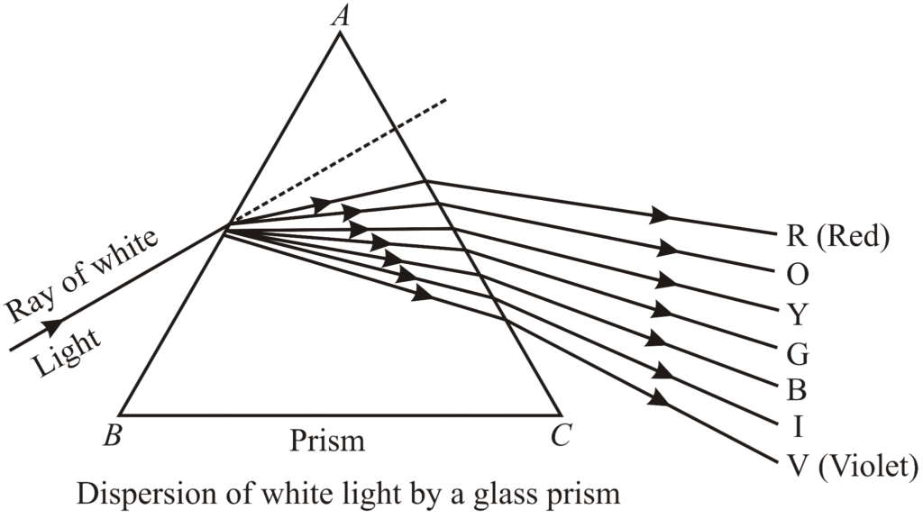
Question 19. A ray of white light falls on a prism. Draw a ray diagram to show that the prism disperses the white light.
Ans:
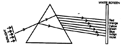
Ray Diagram for Dispersion of White Light by a Prism:
Draw a triangular glass prism.
Let a ray of white light strike one face of the prism.
As the ray enters the prism, it bends towards the normal (refraction).
Inside the prism, white light splits into its constituent colours (VIBGYOR) due to different wavelengths refracting by different amounts.
When these coloured rays leave the prism, they bend away from the normal (second refraction).
On a screen placed on the other side, a spectrum is formed — violet deviates the most, red the least.
Result: The prism disperses white light into its seven constituent colours.
Question 20. In figure AO is the ray of white light falling on a prism PQR. Complete the diagram till the light emerges out from the prism and falls on the screen.
Ans:
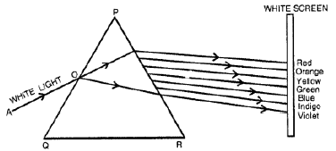
The completed ray diagram is as follows:
Incident Ray: A ray of white light (AO) strikes the face PQ of the prism.
First Refraction: At point O on face PQ, the white light bends towards the normal (inside the prism) and travels as a single ray.
Dispersion: Inside the prism, the single ray splits into its constituent colours (VIBGYOR).
Second Refraction: At point O’ on face PR, the different coloured rays bend away from the normal and exit the prism.
Screen: The diverging coloured rays fall on a screen, forming a spectrum.
The final image on the screen is a band of colours, with violet at the bottom and red at the top.
Question 21. What do you understand by the term spectrum ? Name the various colours present in the spectrum of sunlight.
Ans: The term spectrum refers to the band of colours that is obtained when light is split into its constituent colours by a process of dispersion. A common example of this is the beautiful band of colours we see in a rainbow, which is a natural spectrum formed when sunlight is dispersed by raindrops.
In the context of physics, when a beam of composite white light (like sunlight) passes through a transparent medium, such as a glass prism, the different colours that make up the white light bend, or refract, by different amounts. This is because each colour has its own unique wavelength, and light with shorter wavelengths (like violet) bends more than light with longer wavelengths (like red). This separation of light into its component colours is called dispersion, and the ordered arrangement of these colours is what we call a spectrum.
The various colours present in the spectrum of sunlight, in their correct order from the least deviation to the most, are:
Red
Orange
Yellow
Green
Blue
Indigo
Violet
A simple way to remember this sequence is by using the acronym VIBGYOR, which is the reverse order (starting from Violet), or the more common ROYGBIV (starting from Red).It is important to note that sunlight doesn’t just contain these seven distinct bands of colour. Instead, it consists of a continuous and seamless range of countless shades, which our eyes perceive as these seven major colours.
Question 22. You are given a disc divided into seven sectors with colours violet, indigo, blue, green, yellow, orange and red in them. What would be its colour when it is rotated rapidly ?
Ans:
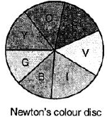
When a disc painted with the seven colours of the rainbow—violet, indigo, blue, green, yellow, orange, and red—is spun quickly, a fascinating trick of perception occurs. Our eyes are remarkable organs, but they have a limitation known as “persistence of vision.” This means that an image or a sensation of light lingers on our retina for a very brief moment, about 1/16th of a second, after the original source is gone.
As the coloured disc rotates rapidly, our eyes simply cannot process each individual colour separately. The signal for one colour hasn’t faded before the next colour zips into view. Instead of seeing distinct bands of violet, blue, or red, the rapid succession of all these coloured stimuli blends together into a single, continuous signal for our brain to interpret.
This blending is a perfect example of additive colour mixing, which is the process of combining different colours of light. Each coloured sector on the disc is reflecting its specific wavelength of light. When these are combined at speed, the effect is similar to shining seven different coloured spotlights onto the same spot. In the world of light, red, green, and blue are the primary colours that can be mixed to create white light. The other colours on the disc (like yellow, cyan, and magenta) fill in the gaps in the spectrum.
Therefore, when the light from all the different coloured sectors merges in our eye, it creates a nearly complete spectrum that our brain interprets as white. The result isn’t always a brilliant, pure white; depending on the exact shades of paint used and the lighting in the room, it often appears as a slightly off-white, pale greyish, or a very muted beige colour. But the overall and most striking effect is that the vibrant rainbow vanishes, replaced by a uniform whitish appearance.
Question 23. State the two laws of reflection of light.
Ans: Understanding the Laws of Reflection
We see the world around us because light bounces off objects and travels into our eyes. The way light bounces off smooth, shiny surfaces like a mirror is described by two simple but fundamental rules called the Laws of Reflection.
The First Law: A Matter of Alignment
The first law states that the incoming ray of light (called the incident ray), the outgoing ray of light (called the reflected ray), and an imaginary line called the normal all exist together on a single, flat plane.
To understand this, let’s break it down:
The Normal: This is an imaginary line that is drawn perpendicular (at a perfect 90-degree angle) to the surface at the exact point where the light ray hits it. Think of it as the “true vertical” for that specific spot on the surface.
The Plane: Imagine a perfectly flat, two-dimensional sheet, like an infinitely thin piece of paper. The first law tells us that if you were to slide this sheet around, you could position it so that the incident ray, the reflected ray, and the normal line all lie perfectly flat on it without any of them sticking out.
In simpler terms, the light ray doesn’t bounce off in some random, twisted direction. The entire “event” of incidence and reflection happens on a single, flat stage.
The Second Law: The Rule of Equal Bounces
The second law is often the more famous one. It says that the angle of incidence is always exactly equal to the angle of reflection.
Here’s what those terms mean:
Angle of Incidence: This is the angle formed between the incoming incident ray and the normal line.
Angle of Reflection: This is the angle formed between the outgoing reflected ray and that same normal line.
The key thing to remember is that we always measure these angles from the normal, not from the surface itself. So, if a beam of light hits a mirror at a 30-degree angle from the normal, it will bounce back off at that same 30-degree angle on the opposite side of the normal. It’s a perfect, symmetrical bounce.
A Simple Analogy
Think of rolling a basketball straight at a wall. If you roll it head-on (a 0-degree angle of incidence), it will bounce straight back to you (a 0-degree angle of reflection). If you roll it at an angle, it will bounce off at that same, but opposite, angle. The physics behind a ball bouncing is different, but the visual outcome is a great way to picture how light behaves.
Question 24. What is a spherical mirror ?
Ans: A concave mirror curves inward like a cave. It collects and focuses light, which is why it’s called a converging mirror. Up close, it magnifies your reflection (like a makeup mirror), but from farther away, the image flips upside down. This focusing ability makes it useful in telescopes and car headlights.
A convex mirror bulges outward. It spreads light out, earning the name diverging mirror. Its key feature is a wide field of view, which is why it’s used in car side-view mirrors and store security. The trade-off is that it makes objects appear smaller and farther away than they really are, leading to the warning “Objects in the mirror are closer than they appear.”
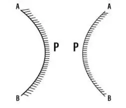
Question 25. State the two kinds of spherical mirror and distinguish them with the aid of proper diagrams.
Ans:
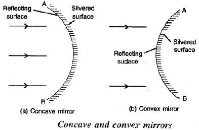
Spherical Mirrors:
Concave Mirror
Shape: Reflecting surface curves inward.
Reflection: Converges parallel light rays to a focus.
Image: Can produce real or virtual images.
Use: Shaving mirrors, headlights.
Diagram:
Parallel rays meet at focus (F) after reflection.
Convex Mirror
Shape: Reflecting surface bulges outward.
Reflection: Diverges parallel rays, which seem to come from a focal point behind the mirror.
Image: Always virtual, erect, and smaller.
Use: Rear-view mirrors, security mirrors.
Diagram:
Parallel rays spread out after reflection, appearing to originate from focus (F) behind the mirror.
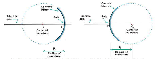
Question 26. Explain the following terms : Pole, Centre of curvature, Radius of curvature, Principal axis. Show them on separate diagrams for each of the concave and convex mirrors.
Ans:
Key Terms for Spherical Mirrors
1. Pole (P)
The geometric center of the reflecting surface of the mirror.
It is the point where the principal axis meets the mirror surface.
2. Centre of Curvature (C)
The center of the imaginary sphere of which the mirror is a part.
It is a point in space, not on the mirror, located in front of a concave mirror and behind a convex mirror.
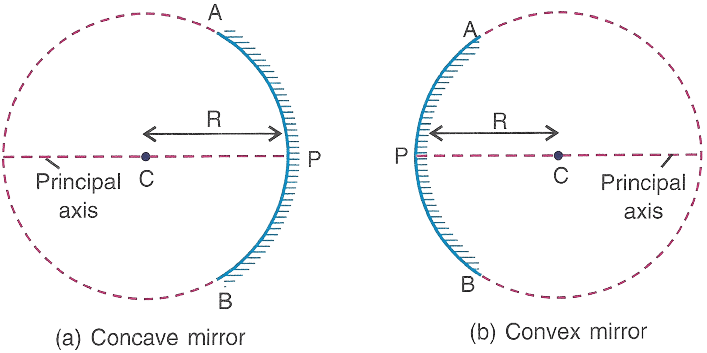
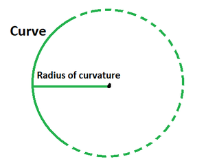
3. Radius of Curvature (R)
It is the radius of the imaginary sphere from which the mirror is cut.
4. Principal Axis
The straight line joining the Pole (P) and the Centre of Curvature (C).
It is the main reference line for the mirror, passing through its center.
Question 27. What do you understand by the focus and focal length of a spherical mirror ? Show them on the separate diagrams for each of a concave mirror and a convex mirror.
Ans: 1. Concave Mirror
In a concave mirror, the focus (F) is real. It is located in front of the reflecting surface, between the pole (P) and the center of curvature (C).
2. Convex Mirror
In a convex mirror, the focus (F) is virtual. It is formed behind the mirror when the reflected rays appear to diverge from a point.
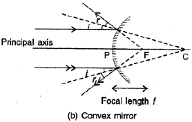
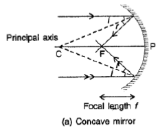
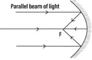
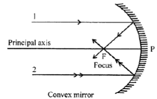
Question 28. Draw suitable diagrams to illustrate how a beam of light incident parallel to the principal axis is reflected by: (a) a concave mirror, and (b) a convex mirror
Ans: (a) Concave Mirror
A concave mirror is curved inwards.
Rays parallel to the principal axis are reflected inwards and converge at a single point called the Focus (F).
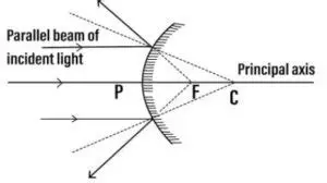
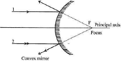
(b) Convex Mirror
A convex mirror bulges outwards.
Rays parallel to the principal axis are reflected outwards. Their diverging paths, when traced backwards, appear to meet at a point behind the mirror called the Focus (F).
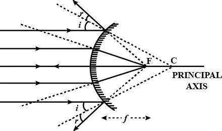
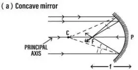
Question 29. How is a spherical mirror used to converge a beam of light at a point ? Name the type of mirror used.
Ans: A concave mirror converges parallel light rays to a single point known as the principal focus. This occurs because its inward-curved surface reflects the rays inward, making them meet at this focus.
Question 30. How is a spherical mirror used to diverge a beam of light from a point ? Name the type of mirror used.
Ans: A spherical mirror diverges a beam of light by reflecting the incoming parallel rays in such a way that they appear to spread out from a single point.In a convex mirror, the reflecting surface bulges outwards. When a parallel beam of light is incident on it, the mirror reflects the rays outwards, making them diverge. The diverging rays, when traced backwards, seem to originate from a common point behind the mirror, known as the focus.
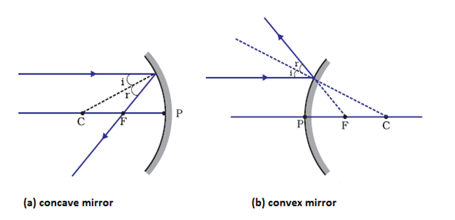
Question 31. State the direction of incident ray which after reflection from a spherical mirror gets reflected along its own path. Give a reason.
Ans: The incident ray must be directed towards the centre of curvature of the spherical mirror.
Reason:
A ray passing through the centre of curvature falls perpendicular to the mirror surface (along the normal) because the radius of curvature is perpendicular to the tangent at the point of incidence.
When the angle of incidence is 0°, the angle of reflection is also 0°, so the ray retraces its own path after reflection.
Question 32. How is the focal length of a spherical mirror related to its radius
Ans: The focal length of a spherical mirror is directly and fundamentally related to its radius of curvature. The relationship is a simple yet crucial principle in optics:
The focal length (f) of a spherical mirror is exactly half of its radius of curvature (R).
This is expressed by the formula:
f = R / 2
or, equivalently,
R = 2f
Explanation of Terms
Radius of Curvature (R): This is the radius of the imaginary sphere of which the spherical mirror is a part. In simpler terms, if you were to complete the curved mirror into a full sphere, the distance from the mirror’s surface to the center of that sphere is the radius of curvature.
Focal Length (f): This is the distance between the pole (the geometric center) of the mirror and its principal focus (F). The principal focus is the point on the principal axis where light rays parallel to the axis converge (in a concave mirror) or appear to diverge from (in a convex mirror) after reflection.
Question 33. The diagram (figure) given below shows two parallel rays 1 and 2 incident on (a) a concave mirror, (b) a convex mirror. Draw the reflected rays and mark the focus by the symbol F.
Ans:
a)
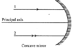
b)
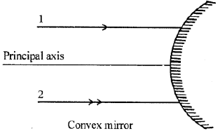
a)
Question 34. Complete the following diagrams in figure by drawing the reflected rays for the incident rays 1 and 2 if F is the focus and C is the centre of curvature
Ans: Reflected rays for incident rays 1 and 2:
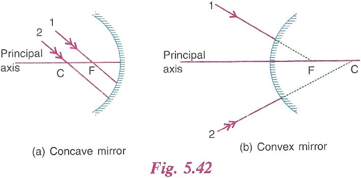
For Incident Ray 1 (parallel to principal axis):
After reflection, this ray passes through the focus F.
For Incident Ray 2 (towards centre of curvature C):
Since it is directed towards C, it strikes the mirror normally.
It retraces its path back through C after reflection.
Question 35. Which are the two convenient rays that are chosen to construct the image by a spherical mirror for a given object ? Explain with the help of suitable ray diagrams.
Ans: Two convenient rays chosen for image construction in spherical mirrors are:
Ray parallel to principal axis: After reflection, this ray passes through the principal focus (in concave mirror) or appears to come from the principal focus (in convex mirror).
Ray passing through the center of curvature: This ray strikes the mirror normally and retraces its path after reflection.
Ray Diagrams:
1. For Concave Mirror (Object between C and F):
Ray 1: From object, parallel to principal axis → after reflection, passes through focus F.
Ray 2: From object, through center of curvature C → strikes mirror and reflects back along same path.
The two reflected rays meet at a point beyond C, forming a real, inverted, and enlarged image.
2. For Convex Mirror (Object in front):
Ray 1: From object, parallel to principal axis → after reflection, diverges as if coming from focus F behind mirror.
Ray 2: From object, towards center of curvature C → reflects back along same path.
The two reflected rays appear to meet behind the mirror, forming a virtual, erect, and diminished image.
These two rays are convenient because they follow predictable reflection rules and easily locate the image without measuring angles.
Question 36. Draw a ray diagram to show the formation of image of an object placed beyond the centre of curvature of a concave mirror. State the position, size and nature of the image.
Ans: Ray Diagram Description:
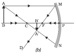
Draw a concave mirror with its principal axis. Mark pole (P), focus (F), and centre of curvature (C).
Place the object beyond C (to the left of C).
Draw two rays from the object’s top:
A ray parallel to the principal axis, which after reflection passes through F.
A ray passing through C, which strikes the mirror and reflects back along the same path.
The reflected rays meet between F and C, forming a real, inverted image.
Position of image: Between F and C
Size of image: Diminished (smaller than the object)
Nature of image: Real and Inverted
Question 37. Draw a ray diagram to show the formation of image of an object placed at the centre of curvature of a concave mirror. State the position, size and nature of the image.
Ans: Ray Diagram:
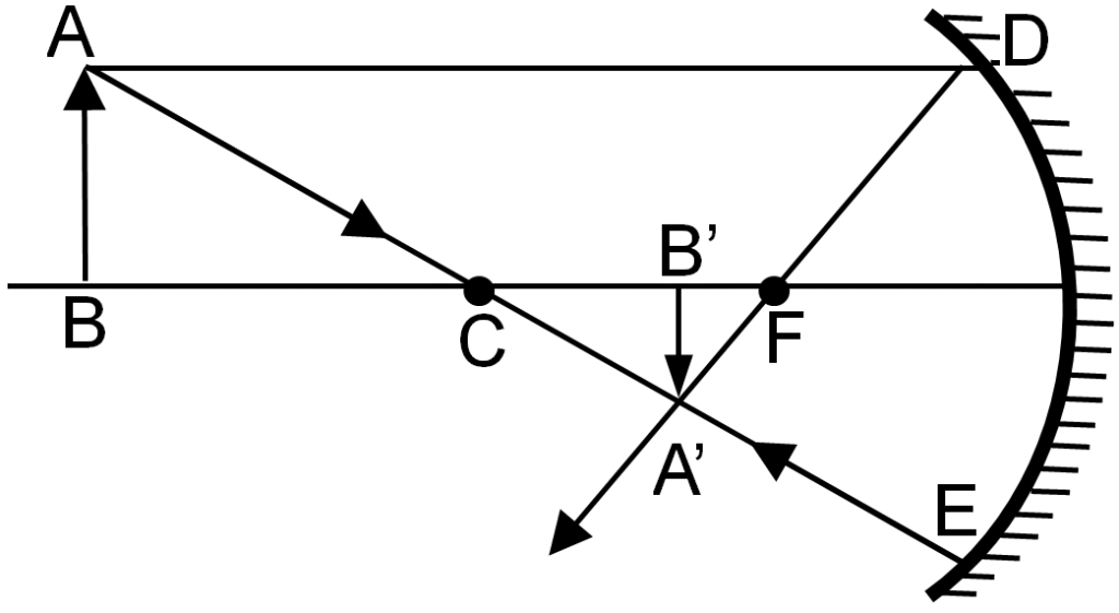
Draw a concave mirror with its principal axis, focus (F), and centre of curvature (C).
Place the object at C, perpendicular to the axis.
Draw two rays:
- One parallel to the principal axis, reflecting through F.
(Alternatively, one ray through C will reflect back along itself.)
The reflected rays meet at C on the same side, forming the image.
Position: At the centre of curvature (C)
Size: Same size as the object
Nature: Real, inverted
Question 38. Draw a ray diagram to show the formation of image of an object placed between the focus and centre of curvature of a concave mirror. State the position, size and nature of the image.
Ans: Ray Diagram Steps:

Draw a principal axis, a concave mirror, and mark F (focus) and C (centre of curvature).
Place the object between F and C (closer to C).
One parallel to the principal axis, after reflection passes through F.
One passing through F, after reflection goes parallel to the principal axis.
The reflected rays diverge on the left side — extend them backwards to meet behind the mirror.
The image is formed behind the mirror where the extended rays meet.
Image Characteristics:
Position: Behind the mirror (virtual image)
Size: Enlarged (larger than the object)
Nature: Virtual and erect
Final Answer:
When an object is placed between the focus (F) and centre of curvature (C) of a concave mirror, the image is formed behind the mirror, it is enlarged, virtual, and erect.
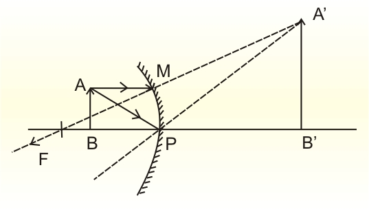
Question 39. Draw a ray diagram to show the formation of image of an object placed between the pole and focus of a concave mirror. State the position, size and natu re of the image.
Ans: Ray Diagram Description:
Draw a concave mirror with its principal axis. Mark the pole (P) and focus (F).
Place the object AB between P and F, just above the principal axis.
Draw a ray from the top of the object (A) parallel to the principal axis. After reflection, it passes through F.
Draw another ray from A passing through the center of curvature (C), which reflects back along the same path.
The two reflected rays diverge after reflection. Extend them backwards (dashed lines) — they meet behind the mirror to form the image.
The image A’B’ is formed behind the mirror, upright, and larger than the object.
Position, Size, and Nature of the Image:
Position: Behind the mirror (virtual image)
Size: Enlarged (larger than the object)
Nature: Virtual and erect
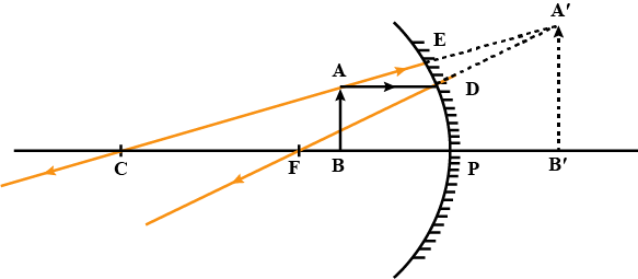
Question 40. Draw a ray diagram to show the formation of image of an object placed on the principal axis of a convex mirror. State the position, size and nature of the image. What happens to the image as the object is moved away from the mirror ?
Ans: Ray Diagram:
Draw a convex mirror with its principal axis.
Mark the center of curvature (C) and focus (F) behind the mirror.
Place an object (an upright arrow) anywhere between the pole (P) and infinity on the principal axis.
One parallel to the principal axis, which after reflection appears to diverge from F.
One directed towards the center of curvature (C), which reflects back along itself.
The reflected rays diverge. Extend them backwards behind the mirror (using dashed lines) to meet at a point.
This point of intersection behind the mirror is the image position. Draw the image as an upright arrow from the principal axis to this point.
Position, Size, and Nature of the Image:
Position: Between the pole (P) and the focus (F), behind the mirror.
Size: Diminished (smaller than the object).
Nature: Virtual, erect.
What happens as the object is moved away from the mirror?
As the object moves away from the mirror towards infinity:
The image decreases in size further.
The image moves from P towards F (but always remains between P and F behind the mirror).
The image remains virtual, erect, and diminished.
Question 41. Draw separate diagrams for the formation of virtual image of an object by (a) concave mirror and (b) convex mirror. State the difference in the two images.
Ans: (a) Formation of Virtual Image by a Concave Mirror
Diagram:
(A hand-drawn diagram would show:)
A concave mirror on the left, with its principal axis.
An object (an arrow) placed between the Pole (P) and the Focus (F) of the mirror.
Two incident rays from the object’s tip:
A ray parallel to the principal axis, which after reflection, passes through the Focus (F).
A ray going towards the Centre of Curvature (C), which reflects back on itself.
The two reflected rays diverge after reflection. When these reflected rays are extended backwards (shown with dotted lines), they appear to meet behind the mirror.
The point where the dotted lines meet forms a virtual, erect, and magnified image behind the mirror.
(b) Formation of Virtual Image by a Convex Mirror
Diagram:
(A hand-drawn diagram would show:)
A convex mirror on the left, with its principal axis.
An object (an arrow) placed anywhere in front of the mirror.
Two incident rays from the object’s tip:
A ray parallel to the principal axis, which after reflection, appears to diverge from the Focus (F) behind the mirror.
A ray going towards the Centre of Curvature (C) behind the mirror, which reflects back on itself.
The reflected rays diverge. When extended backwards (shown with dotted lines), they meet at a point behind the mirror.
This forms a virtual, erect, and diminished image between the Pole (P) and the Focus (F) behind the mirror.
Question 42. Name the mirror which always forms an erect and virtual image. What is the size of the image as compared to that of the object ?
Ans: The type of mirror that is known for always creating an image that is upright (erect) and virtual is the convex mirror.
You can easily recognize a convex mirror because its surface bulges outward, like the back of a shiny spoon or the security mirrors used in stores. Because of this curved shape, the light rays that hit it diverge, or spread out. When our eyes trace these diverging rays backward, our brain perceives a virtual image that appears to be behind the mirror. This image cannot be projected onto a screen, which is a key feature of a virtual image.
Another consistent characteristic of the images formed by convex mirrors is that they are diminished. This means the image you see in the mirror is always smaller in size compared to the actual object. This is precisely why convex mirrors are so useful for applications like car side-view mirrors and surveillance mirrors; they provide a wide field of view, allowing you to see more of your surroundings, albeit in a smaller, compressed view.
Question 43. Name the mirror which forms an erect, virtual and enlarged image of an object. What is the position of object relative to the mirror ?
Ans: The mirror which forms an erect, virtual and enlarged image of an object is a Concave Mirror.
Position of the object relative to the mirror:
For a concave mirror to produce an erect, virtual, and enlarged image, the object must be placed between the pole (P) and the principal focus (F) of the mirror.
In other words, the object distance from the mirror should be less than the focal length (i.e., object position u<f ).
Question 44. What is a real image ? Name the mirror which can be used to obtain the real image of an object. What should be the position of the object relative to the mirror ?
Ans: A real image is formed when light rays actually meet at a point after reflection. It can be projected onto a screen.
The mirror used to obtain a real image is a Concave Mirror.
For a concave mirror to form a real image, the position of the object must be beyond the mirror’s Focus (F). If the object is at infinity, the image is real and at the focus, and if the object is between the focus and the center of curvature, the image is real, inverted, and magnified.
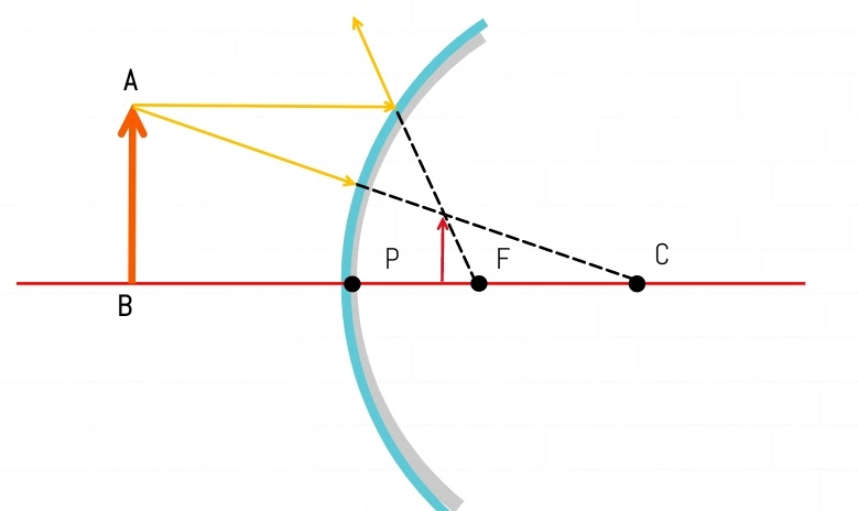
Question 45. How can a concave mirror be used to obtain a virtual image of an object ? Draw a diagram to illustrate your answer.
Ans:
A concave mirror creates a virtual image when an object is placed between its pole (P) and principal focus (F).
In this position, the reflected rays diverge. To find the image, these rays are extended backward behind the mirror.
The backward extensions meet to form an image that is:
Virtual (cannot be projected on a screen)
Erect (upright)
Magnified (larger than the object)
This is why concave mirrors are used as shaving or makeup mirrors—they provide an enlarged view of the face.
Question 46. State two uses of a concave mirror.
Ans: Two uses of a concave mirror are:
As a shaving mirror/makeup mirror: When the face is placed close to the mirror (within its focus), it produces a large, virtual, and erect image, making it easier to see fine details.
As a reflector in torches, searchlights, and car headlights: The light source is placed at the focus of the mirror. This causes the reflected light rays to form a powerful, parallel beam of light, providing strong illumination over a long distance.
Question 47. State two uses of a convex mirror.
Ans: Two uses of a convex mirror are:
As a rear-view mirror in vehicles because it provides a wider field of view, allowing the driver to see more of the traffic behind.
For security and surveillance in shops as it enables a single person to monitor a large area by providing a broad view of the surroundings.
Question 48. A driver uses a convex mirror as a rear view mirror. Explain the reason with the help of a ray diagram.
Ans:
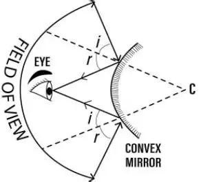
This allows the driver to see a larger area of the traffic behind the vehicle, which is crucial for safe driving.
Reason:
A convex mirror is a diverging mirror. It always forms a virtual, erect, and diminished image, regardless of the object’s position. While the image is smaller, the major advantage is that it covers a much wider field of view compared to a plane mirror. This helps the driver to monitor more vehicles and pedestrians in a single glance.
Ray Diagram Explanation:
The ray diagram for a convex mirror shows why the field of view is wider.
The object (a car) is placed in front of the mirror.
Two rays are drawn from the top of the object:
A ray parallel to the principal axis, which after reflection, appears to diverge from the focus (F).
A ray heading towards the centre of curvature (C), which reflects back on itself.
These reflected rays diverge. When they are extended backwards, they meet to form a virtual, erect, and diminished image behind the mirror.
Because the reflected rays spread out over a large area, the convex mirror allows the driver’s eye to see objects coming from a much wider angle, as illustrated in the diagram. This wide-angle view is the key safety reason for its use.
Question 49. State the kind of mirror used (a) by a dentist, and (b) as a street light reflector.
Ans: (a) Mirror used by a dentist: A dentist uses a Concave Mirror.
The reason is that a concave mirror is a converging mirror. When an object is placed close to it (within its focus), it produces a virtual, erect, and magnified image. This powerful magnification allows the dentist to see a enlarged view of the patient’s teeth, making it easier to examine minor cavities, cracks, and other dental issues in great detail.
(b) Mirror used as a street light reflector: A Convex Mirror is used as a street light reflector.
The reason is that a convex mirror is a diverging mirror that always forms a virtual, erect, and diminished image. The key feature here is that it has a wide field of view. By using a convex mirror, the light from the bulb placed at its focus is spread out over a much larger area. This helps in illuminating a broader section of the road, rather than just a concentrated spot, making it more effective for street lighting.
Question 50. Name the kind of mirror used to obtain (a) a real and enlarged image (b) a virtual ard enlarged image (c) a real and diminished image, and (d) a virtual and diminished image.
Ans: (a) Real and enlarged image → Concave mirror
(b) Virtual and enlarged image → Concave mirror
(c) Real and diminished image → Concave or Convex mirror
(d) Virtual and diminished image → Convex mirror
