
")
Household circuits are designed to distribute electricity safely and efficiently throughout a home using a parallel system. This allows each appliance to operate independently at the same voltage (220V in India).
1. The Three Main Wires:
Live (or Phase) Wire: Carries high voltage (220V) from the power station. It is Red or Brown.
Neutral Wire: It is at zero potential. It is Black or Light Blue.
Earth Wire: A safety wire that connects the metal body of an appliance to the ground. It prevents electric shock by diverting any current leakage into the earth. It is Green or Green-Yellow.
2. Safety Components:
Fuse: It is a safety device with a thin wire that melts and breaks the circuit if the current exceeds a safe limit. It protects appliances from damage due to overloading or short-circuiting.
Circuit Breaker: A modern, automatic switch (like an MCB) that trips and cuts off the circuit during overloading. It can be easily reset.
3. Key Concepts:
Short Circuit: Occurs when the live and neutral wires touch directly, causing a very high current to flow.
Overloading: Happens when too many appliances are connected to a single socket, drawing current beyond the circuit’s safe capacity.
Earthing: The process of connecting the metal body of high-power appliances (like iron, refrigerator) to the earth wire for safety.
In short, household circuits use a parallel arrangement with live, neutral, and earth wires, protected by fuses or circuit breakers, to ensure the safe operation of all electrical appliances.
EXERCISE 9(A)
1.At what voltage and frequency is the electric power generated at the power generating station?
Ans: Electric power is generated at 11,000 volts and a frequency of 50 Hertz (Hz).This voltage is high enough for efficient generation but is immediately “stepped up” to much higher voltages (like 132 kV or 400 kV) for long-distance transmission to reduce energy loss.The frequency is fixed at 50 Hz to ensure that all electrical appliances and machinery connected to the national grid operate correctly and in sync.
2.Explain with the aid of a simple diagram, the transmission of electric power from the generating station to your house.
Ans: The process involves three main stages:
Step-up at Generating Station: Power is generated at around 11,000 Volts. It is first sent to a step-up transformer near the power station. This transformer increases the voltage to a very high level (like 132,000 V or 400,000 V) for long-distance travel. High voltage reduces energy loss as heat in the wires.
Long-Distance Transmission: The electric power is then carried over hundreds of kilometers via tall transmission towers (pylons) and high-voltage power lines.
Step-down for Distribution:
At a city’s outskirts, the high voltage is reduced to a medium voltage (like 11,000 V or 33,000 V) at a substation.
Near your locality, a smaller transformer (often a cylindrical can on a utility pole or a green box on the ground) step-downs this medium voltage to 220/240 Volts, which is safe for homes.
Finally, this 220V power is delivered to your house through service lines.
Simple Diagram:
text
POWER STATION STEP-UP LONG-DISTANCE
(11,000 V) TRANSFORMER TRANSMISSION LINES
| |
|——————->|————————–>
|
|
V
—
YOUR HOUSE <——— STEP-DOWN TRANSFORMER <—– SUBSTATION</mark>
(220 V) (on Pole) (Step-Down)
Explanation: The diagram shows the flow of electricity from the power station, where its voltage is increased for efficient travel. Before entering homes, the voltage is progressively decreased to a safe and usable level.
3.(a) At what voltage is the electric power from the generating station transmitted? Give reason to your answer.
(b) What is the nature of current transmitted from the power station?
Ans:
(a) The electric power from the generating station is transmitted at very high voltages, such as 132 kV, 220 kV, or 400 kV.
Reason: Transmitting power at high voltage reduces the current for the same amount of power. This minimizes energy loss as heat (I²R loss) in the transmission wires, making the process much more efficient.
(b) The nature of the current transmitted from the power station is Alternating Current (AC).
Reason: AC can be easily stepped up to high voltages for transmission and stepped down to lower, safer voltages for domestic and industrial use using transformers. This is not possible with Direct Current (DC).
4.At what (i) voltage and (ii) frequency is the a.c. supplied to our houses?
Ans:
In India, the AC (Alternating Current) electricity supplied to our homes has two main specifications:
(i) Voltage: 220-230 Volts
The potential difference provided at the wall outlets is standardized at 230 volts. This is the level required to safely and efficiently power most household appliances.
(ii) Frequency: 50 Hertz (Hz)
The current changes its direction 50 times per second. This uniform frequency of 50 cycles per second is crucial because it ensures that all our electrical appliances, like clocks and motors, run at the correct speed.
5.Name the device used to (a) increase the voltage at the generating station, and (b) decrease the voltage at the sub station for its supply.
Ans: The two essential devices used in the transmission of electricity are:
(a) Step-up Transformer: This device is used at the generating station to increase the voltage to a very high level (like 132 kV or more) for efficient long-distance transmission.
(b) Step-down Transformer: This device is used at various sub-stations to decrease the high voltage to lower, safer levels (like 11 kV or 240 V) before it is supplied to our homes and factories.
6.(a) Name the three connecting wires used in a household circuit.
(b) Which of the two wires mentioned in part (a) are at the same potential?
(c) In which of the wire stated in part (a), the switch is connected?
Ans:
(a) The three connecting wires used in a household circuit are:
The three essential wires in our home wiring are:
Live wire (or Phase wire): This wire carries the high voltage from the power station into our homes. It is the most dangerous wire.
Neutral wire: This wire completes the circuit by providing a return path for the current back to the power station.
Earth wire (or Ground wire): This is a crucial safety wire. It is connected to a metal plate buried deep in the ground and provides a safe path for any leaking current to flow into the earth, preventing electric shocks.
(b) The potential difference of the Neutral wire with respect to Earth:
The Neutral wire is considered to be at the same voltage as the Earth. Therefore, the potential difference (voltage) between the Neutral wire and the Earth wire is zero.
(c) The position of the switch in a household circuit:
In any household appliance, the switch must always be connected to the Live wire. This is a vital safety rule. By breaking the Live wire connection, the appliance is completely disconnected from the high voltage when switched off. This makes it safe to touch or repair the appliance without the risk of an electric shock.
7.What is the pole fuse? Write down its current rating.
Ans: A pole fuse is a protective electrical device installed on utility poles.It is a type of fuse designed to break the electrical circuit if there is a fault or excessive current flow in the overhead power lines, preventing damage to transformers and other equipment.Its common current rating is 100 Amperes.
8.State the function of each of the following in a house circuiting :
(a) kWh meter, (b) main fuse, and (c) main switch.
Ans: (a) kWh meter (Kilowatt-hour meter)
This is the familiar meter, often with a rotating disc or a digital display, installed at the point where electricity enters the house. It doesn’t measure power for an instant, but rather the total amount of electrical energy used over time. The unit it measures is the kilowatt-hour (kWh), which is why we often call it a ‘unit’ of electricity. The electricity board official takes a reading from this meter, and the difference from the last reading is used to calculate the electricity bill.
(b) Main fuse
The main fuse is a crucial safety device made of a thin wire that has a specific melting point. It is connected in series with the live wire. Its only job is to protect the entire house’s internal wiring. If, due to a fault, the current flowing in the circuit becomes dangerously high, the fuse wire gets hot, melts and breaks the circuit. This action stops the flow of current, preventing damage to appliances and, most importantly, avoiding the risk of fire.
(c) Main switch
This is a heavy-duty switch, usually a double-pole switch, located after the kWh meter. It allows you to cut off the electricity supply to the entire house at once. You use this switch for safety when major electrical work needs to be done in the house, like repairing wiring or replacing fixtures. By turning off the main switch, you ensure that all circuits in the house are dead, making it safe for an electrician to work.
9.In what unit does the electric meter in a house measure the electrical energy consumed? What is its value in S.I. unit?
Ans: The S.I. unit of energy is the joule (J).We can find out how many joules it equals by breaking it down.
Kilo means 1000, so 1 kilowatt (kW) = 1000 watts.
A watt is defined as 1 joule per second (1 W = 1 J/s).
One hour has 3600 seconds.
Therefore, to find the energy in joules, we multiply the power in kilowatts by the time in seconds:
Energy = Power × Time
1 kWh = (1 kW) × (1 hour)
= (1000 J/s) × (3600 s)
= 3,600,000 joules
This large number is more conveniently written as:
1 kWh = 3.6 × 10⁶ J
10.Where is the main fuse connected in a house circuit?
Ans:The main fuse in a house circuit is connected in the live wire, right before the electricity meter.It is the first safety device in the circuit as the power supply enters the house from the street mains. Its purpose is to protect the entire house wiring from damage due to excessive current.
11.State one advantage of using the main switch in house wiring.
Ans: A main switch is a very useful safety device in our house. Its biggest advantage is that it acts as a single master control for all the electricity.With just one flip, we can turn off the power to the entire house at once. This is very helpful for safety. When we need to do any electrical repairs or maintenance, we can turn off the main switch. This ensures that no wire in the house is live, preventing the risk of electric shock.Also, during an emergency like a short circuit or an electrical fire, the main switch allows us to cut off all the power instantly. This quick action can help prevent major accidents and protect both people and appliances.
12.Draw a circuit diagram to explain the ring system of house wiring. State two advantages of it.
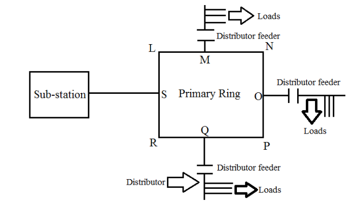
Ans: Circuit Diagram for Ring System of House Wiring:
A circle (ring) is drawn, representing the main circuit.
The Live (L), Neutral (N), and Earth (E) wires from the mains supply run together to form this complete loop or ring.
Various sockets and appliances are connected to this ring at different points.
Two Advantages of the Ring System:
Reduces Wire Length: It uses less conducting wire compared to a radial (tree) system for wiring a similar area, making it more economical.
Efficient Power Distribution: Each socket receives power from two directions (both sides of the ring). This reduces the load on any single section of the wire, allows the use of thinner wires, and prevents overloading.
13.Draw a labelled diagram with the necessary switch, regulator, etc. to connect a bulb and a fan with the mains. In what arrangement are they connected to the mains: series or parallel?
Ans:
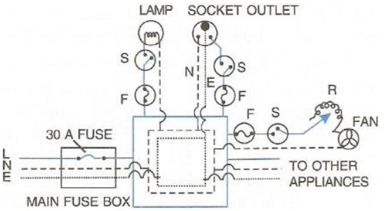
The bulb and the fan are connected to the mains in a parallel arrangement.
This is because in a parallel connection:
Each appliance gets the full voltage (220V) from the mains.
They can be operated independently. You can switch the fan off while the light is on, and vice-versa.
If one appliance fails, the other continues to work.
A simple labelled diagram for the connection is as follows:
Labelled Components:
Live (L) & Neutral (N): Wires from the mains supply.
FUSE: A safety device in the live wire for each appliance to prevent overloading.
SW1 & SW2: Individual switches for the fan and the bulb respectively.
FAN & BULB: The appliances connected across the Live and Neutral wires.
14.How should the several electric lamps be connected with the mains so that the switching on or off a lamp has no effect on the operation of other lamps?
Ans:
Electric lamps are connected in parallel in our household wiring for some very practical reasons:
Full Voltage for Each Lamp: Every lamp gets the full 220V supply voltage directly. This is exactly what they need to glow at their proper brightness. If they were connected in a series circuit, the voltage would be shared, making all the lamps glow dimly.
Independent Operation: You can turn any lamp on or off without affecting the others. This is because each lamp has its own separate path for the electric current. So, switching off one light in the bedroom doesn’t turn off the light in the kitchen.
One Fuse, Others Work: If one lamp burns out (fuses), it breaks the circuit only for that particular lamp. All the other lamps continue to work normally because their individual circuits are still complete. In a series connection, a single fused bulb would break the entire circuit and turn off all the lights.
15.Fig. 9.12 shows three bulbs A, B and C each of rating 100 W, 220 V connected to the mains of 220 V. Answer the following:
(a) How is the bulb A connected with the mains? At what voltage does it glow?
(b) How are the bulbs B and C connected with the mains? At what voltage does the bulb B glow?
(c) How is the glow of bulbs A and C affected if bulb B gets fused?
(d) How is the glow of bulbs B and C affected if bulb A gets fused?
Ans:
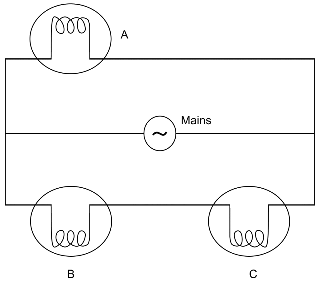
(a) Bulb A is connected in parallel with the mains. It glows at the full mains voltage of 220 V.
(b) Bulbs B and C are connected in series with each other, and this series combination is connected in parallel with the mains. Bulb B glows at 110 V (half of the 220 V mains voltage, as it is shared equally in a series connection with an identical bulb C).
(c) If bulb B gets fused, the series circuit containing B and C is broken. Therefore:
Bulb A is unaffected and glows with the same brightness.
Bulb C will not glow at all.
(d) If bulb A gets fused, it breaks the parallel branch containing only A. Therefore:
The series combination of bulbs B and C remains connected to the full 220 V mains.
Since the voltage is shared equally, bulbs B and C will glow with normal brightness (each receiving 110 V as before).
16.Two sets A and B each of four bulbs are glowing in two separate rooms. When one of the bulbs in set A is fused, the other three bulbs also cease to glow. But in set B, when one bulb fuses, the other bulbs continue to glow.
(i) Explain the difference in the two sets.
(ii) Which set of arrangement is preferred in housing circuit and why?
Ans: (i) Explanation of the difference:
The difference occurs because of the type of electrical connection.
In Set A (Series Connection), the bulbs are connected in a single, continuous path. The current must flow through each bulb one after the other. If one bulb fuses, it breaks the entire path, and the current stops flowing. This causes all the other bulbs to go off.
In Set B (Parallel Connection), each bulb is connected separately across the main power supply, creating multiple paths for the current. If one bulb fuses, only its own path is broken. The other paths remain complete, so the other bulbs continue to glow normally.
(ii) Preferred arrangement and reason:
The Set B (parallel arrangement) is the one we use in our house wiring.
Reasons for this preference:
Independent Operation: You can turn any appliance on or off without affecting the others. For example, you can switch off a light without turning off the fan.
Full Voltage Supply: Every appliance gets the full standard voltage (like 220V) it needs to work correctly. In a series connection, the voltage is shared, which would make appliances like bulbs glow dimly.
No Complete Failure: If one appliance stops working or a bulb fuses, it does not cut off the power to all the other appliances in the house.
Multiple Choice Type:
1.The main fuse is connected in :
(a) live wire
(b) neutral wire
(c) both the live and earth wires
(d) both the earth and neutral wires.
Ans: (a) live wire
2.The electrical appliances in a house are connected in:
(a) series
(b) parallel
(c) either in series or parallel
(d) both in series and parallel.
Ans: (b) parallel
3.The electric meter in a house records :
(a) charge
(b) current
(c) energy
(d) power.
Ans: (c) energy
