

1. What is a Machine?
A machine is a device that allows us to apply a force (effort) at one point to overcome a force (load) at another point. It makes our work easier by changing the magnitude or direction of the applied force. Importantly, a machine does not reduce the amount of work done.
2. Key Concepts and Terms
Effort (E): The force applied to the machine.
Load (L): The force overcome by the machine.
Mechanical Advantage (M.A.): The ratio of the load to the effort (M.A. = L/E). It tells us how many times a machine multiplies the effort.
Velocity Ratio (V.R.): The ratio of the distance moved by the effort to the distance moved by the load (V.R. = dE / dL). It is a constant for an ideal machine.
Efficiency (η): The ratio of useful work done by the machine to the work done on it, expressed as a percentage. (η = (M.A. / V.R.) × 100%). In a perfect, ideal machine with no friction, efficiency is 100%.
3. The Principle of a Machine
For any machine, the work done by the effort is always equal to the work done on the load, plus the work done against friction. This is why the efficiency of a real machine is always less than 100%.
4. Important Simple Machines
Lever: A rigid rod that pivots on a fixed point called a fulcrum. There are three classes of levers (like scissors, wheelbarrow, and human arm) based on the positions of the effort, load, and fulcrum.
Pulley: A wheel with a grooved rim that rotates around an axle. A rope passes through the groove.
Single Fixed Pulley: Only changes the direction of force. Its M.A. and V.R. are both 1.
Single Movable Pulley: Multiplies the force. Its V.R. is 2.
Inclined Plane: A sloping surface that allows a heavy load to be lifted by applying a smaller force over a longer distance. Its V.R. is the ratio of the length of the slope to its height.
5. The Relationship for an Ideal Machine
In an ideal, frictionless machine: M.A. = V.R. and Efficiency = 100%.
EXERCISE-3(A)
1.(a) What do you understand by a simple machine?
(b) State the principle of an ideal machine.
Ans:(a) What do you understand by a simple machine?
A simple machine is a basic mechanical device that does not have a source of power and is used to change the magnitude, direction, or distance of a force to make work easier. It allows us to apply a smaller force (effort) over a longer distance to overcome a larger force (load). There are six classical types of simple machines: the lever, the wheel and axle, the pulley, the inclined plane, the wedge, and the screw. They are the fundamental building blocks of which all more complex machines are composed.
(b) State the principle of an ideal machine.
The principle of an ideal machine, also known as the principle of conservation of energy for machines, states that in the absence of friction and other dissipative forces, the work done on the machine by the effort (input work) is exactly equal to the work done by the machine on the load (output work). This means that an ideal machine has an efficiency of 100%, as no energy is lost.
2.State four ways in which machines are useful to us.
Ans:Machines are useful to us in numerous ways. Firstly, they save us a great deal of time and effort by performing tasks much faster and more efficiently than humans can, such as washing clothes or ploughing fields. Secondly, they enhance our ability to travel and transport goods over long distances, using vehicles like cars, ships, and airplanes. Thirdly, they help in manufacturing, enabling the mass production of consistent quality goods, from clothes to electronics, which would be impossible to make by hand. Finally, machines have vastly improved global communication, allowing us to connect with anyone across the world instantly through computers and smartphones.
3.Name a machine for each of the following use:
(a) to multiply the force,
(b) to change the point of application of force,
(c) to change the direction of force,
(d) to obtain the gain in speed.
Ans:(a) To multiply force:
A car jack uses a small input force on its handle to produce a large output force, lifting a heavy vehicle easily.
(b) To change the point of application of force:
On a seesaw, pushing down at one end applies force at the other end, lifting the person opposite.
(c) To change the direction of force:
A fixed pulley, like on a well, changes a downward pull on the rope into an upward lift on the bucket.
(d) To obtain a gain in speed:
On a bicycle, pedaling turns a small front gear, which rotates a larger rear wheel faster, increasing speed.
4.What is the purpose of a jack in lifting a car by it?
Ans:
- The purpose of a jack when lifting a car is to act as a mechanical device that multiplies a small input force into a large output force, allowing a single person to raise a heavy vehicle with relative ease.
- Its primary function is to create a stable and elevated space beneath the car. This is essential for performing maintenance tasks that are impossible when the car is on the ground, such as:
- Changing a Flat Tyre: This is the most common use. The jack lifts the car so the flat tyre can be removed and replaced with the spare.
- Inspecting the Undercarriage: Mechanics use jacks to lift a vehicle to examine components like the exhaust system, brakes, and suspension.
- Performing Repairs: For more extensive work, a jack is used to raise the car so that it can be placed on more secure jack stands, providing safe and stable access to the underside.
5.What do you understand by an ideal machine? How does it differ from a practical machine?
Ans: An ideal machine is a perfect theoretical concept where efficiency reaches 100%. In this scenario, the work output is exactly equal to the work input, as there are no energy losses. However, all real-world machines are practical machines. In these, the work output is always less than the work input because some energy is used to overcome opposing forces like friction and air resistance. This inherent energy loss means the efficiency of any practical machine is always below 100%.
6.Explain the term mechanical advantage. State its unit.
Ans:Mechanical Advantage (M.A.) is the measure of the force amplification achieved by using a tool, mechanical device, or machine system. In simpler terms, it tells us how many times a machine multiplies the effort (input force) you apply.
It is calculated as the ratio of the load (the resistance or output force overcome by the machine) to the effort (the input force applied to the machine). Therefore, M.A. = Load / Effort.
Since mechanical advantage is a ratio of two forces, it is a dimensionless quantity. It has no unit. A mechanical advantage greater than 1 means the machine multiplies the input force, making it easier to lift or move a heavy load.
7.Define the term velocity ratio. State its unit.
Ans:Velocity Ratio (VR) is a fundamental concept in mechanics that describes the effectiveness of a simple machine in displacing a load through a certain distance relative to the effort applied. It is formally defined as the ratio of the distance moved by the effort to the distance moved by the load in the same time interval. In simpler terms, it indicates how much farther and faster the point where you apply the force (the effort) has to move compared to the point where the load is being moved. For instance, in a pulley system, to raise a load by 1 meter, you might have to pull the rope 3 meters; the velocity ratio in this case would be 3. It is crucial to understand that velocity ratio is a purely geometric property, determined solely by the physical dimensions and configuration of the machine, such as the number of pulleys, the length of a lever arm, or the pitch of a screw. Since it is a ratio of two similar quantities (distances), the Velocity Ratio has no unit; it is a dimensionless quantity. This characteristic distinguishes it from other ratios like mechanical advantage, as the velocity ratio remains constant for a given machine, ignoring the effects of friction and the weight of the machine parts.
8.How is mechanical advantage related to the velocity ratio for (i) an ideal machine, (ii) a practical machine?
Ans:In an ideal machine, energy loss is absent, so the input work equals the output work. This perfect energy transfer results in the mechanical advantage (MA) being exactly equal to the velocity ratio (VR).
In a practical machine, however, friction consumes some input energy. This loss means the useful work output is always less than the work input. Consequently, the mechanical advantage is always lower than the velocity ratio, making the efficiency always less than 100%.
9.Define the term efficiency of a machine. Give two reasons for a machine not to be 100% efficient.
Ans:A machine’s efficiency is the percentage of useful work it produces compared to the energy supplied. No machine can ever be 100% efficient. This is primarily because some input energy is always wasted in overcoming friction between moving parts, which gets converted into heat and sound. Additionally, a portion of the energy is used to move the machine’s own components, rather than being applied directly to the intended load.
10.When does a machine act as (a) a force multiplier,
(b) a speed multiplier. Can a machine act as a force multiplier and a speed multiplier simultaneously?
Ans:A machine acts as a force multiplier when the effort needed is less than the load being moved. This is achieved when the effort moves a greater distance than the load, as seen in tools like a car jack or a crowbar.
A machine acts as a speed multiplier when the load moves a greater distance than the effort. In this case, a larger movement of the effort results in a faster, but smaller movement of the load, as seen in devices like fishing rods or bicycles.
However, a single machine cannot act as both a force multiplier and a speed multiplier at the same time. This is because of the principle of conservation of energy. Gaining force means losing speed, and gaining speed means losing force. A machine can only multiply one at the expense of the other.
11. State the relationship between mechanical advantage, velocity ratio and efficiency. Name the term that will not change for a machine of a given design.
Ans:For any machine, the relationship connecting mechanical advantage (M.A.), velocity ratio (V.R.), and efficiency (η) is expressed as Efficiency = (M.A. / V.R.) x 100%. The mechanical advantage is the practical measure of how much a machine multiplies the force you apply, calculated as the load lifted divided by the effort used. In contrast, the velocity ratio is a fixed theoretical value determined solely by the machine’s physical design and geometry, representing the ratio of the distance the effort moves to the distance the load moves. Because it depends only on the machine’s construction, the velocity ratio remains constant for a given machine, while mechanical advantage and efficiency can vary with factors like friction.
12.Derive a relationship between mechanical advantage, velocity ratio and efficiency of a machine.
Ans:The relationship between Mechanical Advantage (M.A.), Velocity Ratio (V.R.), and Efficiency (η) of a machine is direct and fundamental. It is given by the formula:
Efficiency (η) = (Mechanical Advantage / Velocity Ratio) × 100%
This relationship arises from the definitions of the three terms. The Velocity Ratio (V.R.) is a constant for a machine, determined by its geometry, and represents the ideal or theoretical advantage. The Mechanical Advantage (M.A.) is the real-world advantage we actually get, which is always less than the V.R. due to energy losses from friction.
Therefore, efficiency is essentially the ratio of the machine’s actual performance (M.A.) to its ideal performance (V.R.). A higher efficiency means the M.A. is closer to the V.R., indicating lower energy losses.
13.How is the mechanical advantage related with the velocity ratio for an actual machine? State whether the efficiency of such a machine is equal to 1, less than 1 or more than 1.
Ans:In an actual machine, the mechanical advantage (MA) is always less than the velocity ratio (VR). This happens because some of the input energy is used to overcome friction and other resistive forces, making the useful output work less than the input work.
Therefore, the efficiency of such an actual machine is always less than 1. Efficiency is the ratio of MA to VR, and since MA is less than VR, the ratio becomes a fraction less than one.
14.State one reason why mechanical advantage is less than the velocity ratio for an actual machine.
Ans:In an actual machine, the mechanical advantage is less than the velocity ratio due to the presence of friction. Some of the effort applied to the machine is used to overcome this friction between its moving parts, rather than to lift the load. Consequently, a larger effort is needed than in an ideal, frictionless situation, which makes the ratio of load to effort (mechanical advantage) lower than the ratio of the distance moved by effort to the distance moved by load (velocity ratio).
15.What is a lever? State its principle.
Ans:A lever is a basic machine built around a rigid bar that rotates on a fixed fulcrum. Its primary purpose is to lift or move a load with reduced effort. The core principle, often called the law of the lever, explains that balance is achieved when the effort force multiplied by the length of the effort arm equals the load force multiplied by the length of the load arm. This relationship means you can lift a very heavy object with a small force, as long as you apply that force farther away from the fulcrum. Essentially, you trade distance for force, gaining a mechanical advantage to make work easier.
16.Write down a relation expressing the mechanical advantage of a lever.
Ans:A lever’s mechanical advantage shows how effectively it reduces the effort needed to move a load. It is calculated by dividing the length of the effort arm by the length of the load arm. When this ratio is greater than one, it means the lever is working in your favor, multiplying your input force and making the task significantly easier. Essentially, a longer effort arm relative to the load arm means you need to apply much less force to lift a heavy object.
17.Name the three classes of levers and state how are they distinguished. Give two examples of each class.
Ans:The three classes of levers are defined by the arrangement of their three key parts: the fulcrum (pivot), the effort (applied force), and the load (resistance). In a first-class lever, the fulcrum sits between the effort and the load, as seen in a seesaw. For a second-class lever, the load is positioned between the fulcrum and the effort, which is how a wheelbarrow operates. Finally, in a third-class lever, the effort is applied between the fulcrum and the load; a common example is the human arm when lifting an object.
18.Give one example each of a class I lever where mechanical advantage is (a) more than 1, and (b) less than 1.
What is the use of the lever if its mechanical advantage is (a) more than 1, (b) equal to 1, and (c) less than 1.
Ans:A Class I lever with a Mechanical Advantage (MA) greater than 1, like a pair of scissors, is designed to multiply force. The effort arm is longer than the load arm, allowing a small input force to overcome a larger resistive load, though the effort must move a greater distance.
A Class I lever with an MA less than 1, such as a pair of tweezers, is used to increase speed or displacement. Here, the effort arm is shorter, meaning a larger effort force is needed, but the load moves a greater distance and faster than the point where the effort is applied.
The use of a lever depends directly on its Mechanical Advantage. An MA greater than 1 is for force amplification, enabling heavy loads to be moved with less effort. An MA equal to 1 is primarily for changing the direction of an applied force, offering no force multiplication but often improving convenience. An MA less than 1 sacrifices force to achieve a gain in the speed or distance the load moves, which is useful in precision tools.
19.A pair of scissors and a pair of pliers belong to the same class of levers. Name the class of lever. Which one has the mechanical advantage less than 1?
Ans:Both a pair of scissors and a pair of pliers are Class I levers. In this class, the fulcrum is located between the effort and the load.
Between the two, a pair of scissors has a mechanical advantage of less than 1. This is because the effort arms (the scissor handles) are shorter than the load arms (the scissor blades), making it harder to cut tough materials but allowing for a greater cutting distance.
20.Explain why scissors for cutting cloth may have blades longer than the handles, but shears for cutting metals have short blades and long handles.
Ans:Scissors designed for cutting cloth feature long blades and short handles to create a smooth, continuous slicing action. This design glides effortlessly through soft fabrics, prioritizing a clean and lengthy cut over power. Conversely, metal shears are built with short, robust blades and long handles. This configuration generates significant mechanical advantage, using leverage to multiply the user’s force to cut through tough metal. The shorter blade also adds crucial strength, preventing the tool from bending or breaking under the intense pressure required for the task.
21.Fig.shows a uniform metre rule of weight W supported on a fulcrum at the 60 cm mark by applying the effort E at the 90 cm mark.
(a) State with reason whether the weight W of the rule is greater than, less than or equal to the effort E
(b) Find the mechanical advantage in an ideal case.
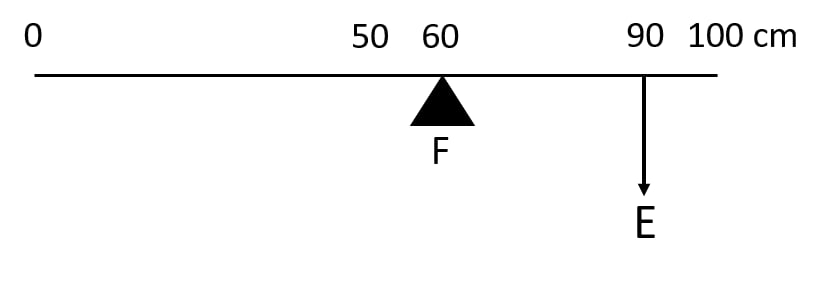
Ans:(a) The weight
W of the metre rule is greater than the effort E
Reason: The centre of gravity of the uniform rule is at the 50 cm mark, which is to the left of the fulcrum (60 cm mark), so its weight produces an anticlockwise moment about the fulcrum. The effort E at the 90 cm mark produces a clockwise moment.
W must be balanced by the clockwise moment due to E. Since the lever arm of W about the fulcrum (10 cm) is smaller than that of E (30 cm), W must be larger than E to balance the moments.
(b) In the ideal case (no friction, etc.),
Mechanical Advantage (MA) =Load arm/Effort arm
Here, the load is W, acting at 50 cm mark.
Load arm = distance from fulcrum (60 cm) to load = 60−50=10 cm
Effort arm = distance from fulcrum (60 cm) to effort (90 cm) = 90−60=30 cm
MA= 10/30 =3
22.Which type of lever has a mechanical advantage always more than 1? Give one example. What change can be made in this lever to increase its mechanical advantage?
Ans:A class II lever always provides a mechanical advantage greater than one because the load is positioned between the fulcrum and the applied effort. This arrangement ensures the effort arm is always longer than the load arm, making it easier to move heavy loads. A common example is a wheelbarrow, where the wheel is the fulcrum, the load sits in the barrel, and you lift using the handles as the effort point. To increase the mechanical advantage further, you simply move the load closer to the fulcrum. For instance, placing heavy material nearer to the wheel of a wheelbarrow reduces the effort needed, making it even easier to lift.
23. Draw a diagram of a lever which is always used as a force multiplier. How is the effort arm related to the load arm in such a lever?
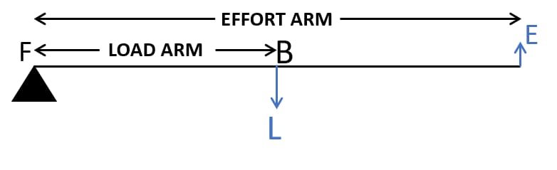
Ans:A Class 2 lever is always a force multiplier. In this design, the load sits between the fulcrum and the effort. For example, imagine a wheelbarrow; the wheel is the fulcrum, the load is in the bucket, and you lift on the handles. Because the effort arm is always longer than the load arm, a smaller input force can overcome a larger load, making it permanently designed to multiply force.
24.. Explain why the mechanical advantage of a class II type of lever is always more than 1.
Ans:In a class II lever, the load is situated between the effort and the fulcrum. This arrangement means the effort arm (the distance from the fulcrum to the effort) is always longer than the load arm (the distance from the fulcrum to the load).
Since mechanical advantage is the ratio of the effort arm to the load arm, this ratio will always be greater than one. Essentially, the effort is always applied farther from the fulcrum than the load is, giving the effort a natural leverage advantage. This is why class II levers, like a wheelbarrow or a nutcracker, are designed to multiply force, making it easier to move heavy loads.
25. Draw a labelled diagram of a class II lever. Give one example of such a lever.
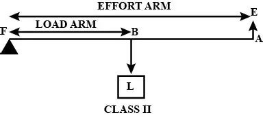
Ans:Diagram Description:
A class II lever has the load between the effort and the fulcrum. The labelled diagram should show:
A long bar representing the lever.
Fulcrum (F): Marked at one end of the bar.
Load (L): Marked in the middle of the bar.
Effort (E): Marked at the opposite end from the fulcrum.
The arrows for effort and load should point downwards, while the fulcrum is shown as a triangle supporting the bar from below.
Example:
The wheel acts as the fulcrum, the load (the contents) is placed in the bucket between the wheel and the handles, and the effort is applied upwards at the handles to lift the load.
26. Fig. 3.13 shows a lemon crusher.
(a) In the diagram, mark the position of the fulcrum F and the line of action of load L and effort E.
(b) Name the class of lever.

Ans: (a) In the lemon crusher (Fig. 3.13), the fulcrum (F) is located at the hinge where the two arms are joined. The load (L) acts at the head which presses the lemon, and the effort (E) is applied by the hands on the handles.
(b) This is a class II lever because the load is situated between the fulcrum and the effort.
27. The diagram below shows a rod lifting a stone.
(a) Mark position of fulcrum F and draw arrows to show the directions of load L and effort E.
(b) What class of lever is the rod?
(c) Give one more example of the same class of lever stated in part (b).
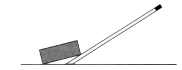
Ans:(a) In the diagram, the fulcrum F is at the point where the rod pivots against the ground. The load L (the stone) acts downwards at the end of the rod under the stone, and the effort E is the downward force applied by the person at the opposite end of the rod.
(b) This is a Class I lever because the fulcrum is positioned between the effort and the load.
(c) Another common example of a Class I lever is a seesaw.
28. State the kind of lever which always has the mechanical advantage less than 1. Draw a labelled diagram of such a lever.
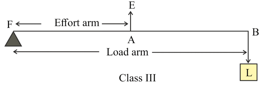
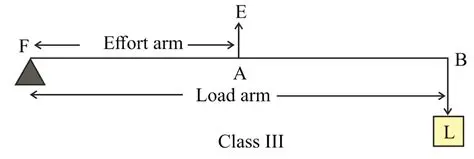
Ans:A Class III lever always has a mechanical advantage (MA) of less than 1. This occurs because the effort is applied between the fulcrum and the load, making the effort arm shorter than the load arm. Consequently, you need to apply a larger force to move a smaller load. The benefit, however, is that this setup allows the load to be moved a greater distance and at a higher speed.
In a simple diagram, the fulcrum is at one end, the load is at the other end, and the effort is applied in the middle. Common real-world examples are a pair of tweezers, a human forearm when lifting a weight, or a fishing rod in use.
29. Explain why the mechanical advantage of the class III type of lever is always less than 1.
Ans: This means the effort arm (the distance from the fulcrum to the effort) is always shorter than the load arm (the distance from the fulcrum to the load).
Since mechanical advantage (MA) is the ratio of the load arm to the effort arm (MA = Load Arm / Effort Arm), having a shorter effort arm results in a ratio that is always less than 1.
Therefore, a class III lever always requires more effort force than the load it moves. Its key advantage is not force multiplication, but increased speed and range of motion for the load, as seen in tools like tweezers and fishing rods.
30. Class III levers have the mechanical advantage less than 1. Why are they then used?
Ans:Class III levers always have a mechanical advantage of less than 1, meaning they cannot multiply force. Despite this, they are widely used because their primary purpose is not to increase force, but to increase speed and range of motion.
In such levers, the effort arm is shorter than the load arm. When a small movement is applied at the effort, it results in a larger and faster movement at the load end. This principle is crucial in many tools and within our own bodies. For instance, tweezers and brooms are class III levers; they sacrifice force for greater precision or sweeping coverage. Similarly, our forearm acts as a class III lever. When our bicep contracts a small amount, it causes our hand to swing through a much larger and faster arc, enabling us to throw a ball or wave quickly. Therefore, these levers are used for gaining speed and distance, not force.
31: What type of lever is formed by the human body while (a) raising a load on the palm, (b) raising the weight of body on toes?
Ans:(a) When lifting an object on your palm, the arm works as a Class III lever. The elbow is the fulcrum, the bicep applies effort between the elbow and the load in the hand.
(b) When standing on your toes, the foot acts as a Class II lever. The toes are the fulcrum, the calf muscles supply effort, and the body weight is the load between the toes and the effort.
32: Indicate the positions of load, effort and fulcrum in the forearm shown below in Fig 3.15 Name class of lever.
Ans:
In the forearm:
Fulcrum: Elbow joint (point where rotation occurs)
Effort: Biceps muscle (point where force is applied)
Load: Weight in the hand (object being moved)
Class of Lever: It is a Class 3 lever because the effort is located between the fulcrum and the load.
33. Draw a labelled sketch of a class III lever. Give one example of this kind of lever.
Ans:
A class III lever has the effort placed between the fulcrum and the load. In a labelled sketch, the arrangement from one end to the other is: Fulcrum – Effort – Load.
A common example of a class III lever is a pair of tweezers. When you use tweezers, the point where your fingers press (the effort) is between the pivot point at the top (the fulcrum) and the tips that grip the object (the load). Another everyday example is a human arm; your elbow joint acts as the fulcrum, your biceps muscle provides the effort on the forearm, and your hand holds the load.
34: Give example of each class of lever in a human body?
Ans:In the human body, the three lever classes are illustrated by specific movements. A first-class lever occurs when you nod your head, with the top of the spine as the fulcrum, neck muscles providing effort, and the head’s weight acting as the load. A second-class lever is demonstrated by rising onto your toes, where the ball of your foot is the fulcrum, the calf muscles create the effort to lift the body’s weight as the load. The most common type is the third-class lever, seen when bending your elbow to lift a weight; here, the elbow joint is the fulcrum, the biceps muscle applies the effort, and the weight in your hand is the load.
35. State the class of levers and the relative positions of load (L), effort (E) and fulcrum (F) in (a) a bottle opener, and (b) sugar tongs.
Ans:A bottle opener functions as a class II lever. In this design, the fulcrum is at the far end on the bottle rim, the load is the cap’s resistance at the tip, and the effort is applied downwards in the middle. This configuration positions the load between the fulcrum and the applied effort. Conversely, sugar tongs operate as a class III lever. Here, the fulcrum is at the hinged end, the effort is applied by the fingers in the middle, and the load, which is the sugar, is held at the tips. This means the effort is situated between the fulcrum and the load.
36. Draw diagrams to illustrate the positions of fulcrum, load and effort, in each of the following :
(a) A seesaw
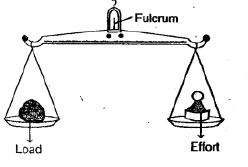
(b) A common balance
(c) A nut cracker
(d) Forceps.
Ans:
37. Classify the following into levers as class I, class II or class III :
(a) a door
(b) a catapult
(c) a wheel barrow
(d) a fishing rod.
Ans: (a) Door – Class II lever
(b) Catapult – Class I lever
(c) Wheel barrow – Class II lever
(d) Fishing rod – Class III lever
MULTIPLE CHOICE TYPE
1. Mechanical advantage (M.A.), load (L) and effort (E) are related as :
(a) M.A. = L × E
(b) M.A. × E = L
(c) E = M.A. × L
(d) none of these.
Ans:(b) M.A. × E = L
2. The correct relationship between the mechanical advantage (M.A.), the velocity ratio (VR.) and the efficiency (η) is :
(a) M.A. = η × VR.
(b) VR. = η × MA.
(c) η = M.A. × VR.
(d) none of these.
Ans:(a) M.A. = η × VR.
Question 3: Which of the following statements is not true for a machine:
(a) It always has efficiency less than 100%
(b) its mechanical advantage can be less than 1.
(c) It can also be used as a speed multiplier (d) It can have a mechanical advantage greater than the velocity ratio.
Ans:The statement that is not true for a machine is (d) It can have a mechanical advantage greater than the velocity ratio.
This is because the Mechanical Advantage (MA) is the ratio of load to effort, while the Velocity Ratio (VR) is the ratio of the distance moved by effort to the distance moved by the load. Due to energy losses from friction, the MA is always less than or equal to the VR in a real machine. It is impossible for MA to be greater than VR.
The other statements are correct:
(a) is true due to energy loss from friction.
(b) is true for machines like a single movable pulley where the load is less than the effort.
(c) is true for devices like bicycles, which multiply speed at the cost of increased effort.
4. The lever for which the mechanical advantage is less than 1 has the :
(a) fulcrum at mid point between the load and effort.
(b) load between the effort and fulcrum.
(c) effort between the fulcrum and load.
(d) load and effort acting at the same point.
Ans:(c) effort between the fulcrum and load.
5. Class II levers are designed to have :
(a) M.A. = VR.
(b) M.A. > VR.
(c) M.A. > 1
(d) M.A. < 1
Ans:(c) M.A. > 1
NUMERICALS
Numericals
1. A crowbar of length 120 cm has its fulcrum situated at a distance of 20 cm from the load. Calculate the mechanical advantage of the crowbar.
Ans:The mechanical advantage (MA) of the crowbar is 6.
This is calculated using the formula for a lever, MA = Effort Arm / Load Arm. Here, the total length is 120 cm and the load arm (distance from fulcrum to load) is 20 cm. Therefore, the effort arm is 120 cm – 20 cm = 100 cm.
Mechanical Advantage = 100 cm / 20 cm = 5.
Question 2: A 4 m long rod of negligible weight is to be balanced about a point 125 cm from one end. A load of 18 kgf is suspended at a point 60 cm from the support on the shorter arm. (a) a weight W is placed 250 cm from the support on the longer arm Find W. (b) If W = 5 kgf, where must it be kept to balance the rod? (c) To which class of lever does it belong?
Ans:Step 1: Understand the setup
Length of rod = 4 m = 400 cm
Support (fulcrum) is 125 cm from end A.
Let’s call end A the left end.
So:
Shorter arm length = 125 cm (from A to fulcrum)
Longer arm length = 400 – 125 = 275 cm (from fulcrum to other end)
(a) Load and weight positions given
Load = 18 kgf, 60 cm from support on shorter arm →
This means it is between A and fulcrum: 125 – 60 = 65 cm from A, so indeed 60 cm left of fulcrum.
Clockwise moment (longer arm):W×250 (250 cm from support on longer arm)
Anticlockwise moment (shorter arm):18×60
Balance:W×250=18×60
W=1080/250
=4.32 kgf
(b) If
W=5 kgf, find its distance
x from support on longer arm
Moments:5×x=18×60
x=1080/5=216 cm
(c) Class of lever
Fulcrum is between load and effort → Class I lever.
Final Answers:
(a) W=4.32 kgf
(b) x=216 cm from support on longer arm
(c) Class I lever
3. A pair of scissors has its blades 15 cm long, while its handles are 7.5 cm long. What is its mechanical advantage?
Ans:
Given:
Effort arm (handle length) = 7.5 cm
Load arm (blade length) = 15 cm
In a pair of scissors, the mechanical advantage (MA) is the ratio of the load arm to the effort arm when the effort is applied at the handle:
MA=Load arm/Effort arm
=15/7.5
=2
Answer: The mechanical advantage is 2.
4. A force of 5 kgf is required to cut a metal sheet. A shears used for cutting the metal sheet has its blades 5 cm long, while its handles are 10 cm long. What effort is needed to cut the sheet?
Ans:To cut the sheet metal with a 5 kgf force, the required effort is calculated using the lever principle. Given a load arm of 5 cm and an effort arm of 10 cm, the equation becomes Effort × 10 = 5 × 5. Solving this, the effort needed is 2.5 kgf.
5. Fig. 3.16 below shows a lever in use.
(a) To which class of lever does it belong?
(b) If AB = 1 m, AF = 0.4 m, find its mechanical advantage.
(c) Calculate the value of E
Ans:(a) The lever belongs to Class 2. This is because the load (L) is situated between the fulcrum (F) and the effort (E).
(b) Given:
AB (load arm) = 1 m
AF (effort arm) = 0.4 m
Mechanical Advantage (M.A.) is given by the ratio of the effort arm to the load arm.
M.A.=Effort Arm/Load Arm
=AF/AB
=0.4/1
=0.4
So, the mechanical advantage is 0.4.
(c) The mechanical advantage can also be expressed as:
M.A.=Load/Effort
=L/E
From part (b), M.A. = 0.4, and the Load (L) is given as 20 kgf (as shown in the figure).
0.4=20/E
E=20/0.4
=50 kgf
Thus, the value of effort E is 50 kgf.
6. A man uses a crowbar of length 1.5 m to raise a load of 75 kgf by putting a sharp edge below the bar at a distance of 1 m from his hand.
(a) Draw a diagram of the arrangement showing the fulcrum (F), load (L) and effort (E) with their directions.
(b) State the kind of lever.
(c) Calculate : (i) load arm, (ii) effort arm, (iii) mechanical advantage, and (iv) the effort needed.
Ans:(a) Diagram Description:
The crowbar is a horizontal lever. The fulcrum (sharp edge) is 1 meter from the man’s hands. The effort is applied downward at one end, and the 75 kgf load acts downward at the far end, 1.5 meters from the man’s hands.
(b) Kind of Lever:
This is a Class I lever, since the fulcrum lies between the effort and the load.
(c) Calculations:
(i) Load Arm = Total length − Effort distance = 1.5 m − 1 m = 0.5 m.
(ii) Effort Arm = 1 m (given).
(iii) Mechanical Advantage (M.A.) = Effort Arm ÷ Load Arm = 1 m ÷ 0.5 m = 2.
(iv) Effort Needed = Load ÷ M.A. = 75 kgf ÷ 2 = 37.5 kgf.
7. A pair of scissors is used to cut a piece of a cloth by keeping it at a distance of 8.0 cm from its rivet and applying an effort of 10 kgf by fingers at a distance of 2.0 cm from the rivet.
(a) Find : (i) the mechanical advantage of scissors, and (ii) the load offered by the cloth.
(b) How does the pair of scissors act : as a force multiplier or as a speed multiplier?
Ans:(a) (i) The mechanical advantage is 0.25, calculated as the ratio of the effort arm (2.0 cm) to the load arm (8.0 cm).
(ii) With an effort of 10 kgf, the load offered by the cloth is 2.5 kgf, found by multiplying the mechanical advantage by the applied effort.
(b) Since the mechanical advantage is less than one, the pair of scissors functions as a speed multiplier. This means the blades move a greater distance and faster than the handles, prioritizing speed over force for a quick cut.
8. Fig. 3.17 below shows a lever in use.
(a) To which class of lever does it belong?
(b) If FA = 80 cm, AB = 20 cm, find its mechanical advantage.
(c) Calculate the value of E
Ans:(a) The lever shown belongs to Class 2. This is because the load (L) is situated between the fulcrum (F) and the effort (E).
(b) Given:
FA (Effort Arm) = 80 cm
AB = 20 cm
Therefore, FB (Load Arm) = FA – AB = 80 cm – 20 cm = 60 cm.
The Mechanical Advantage (M.A.) is calculated as:
M.A. = Effort Arm / Load Arm = FA / FB = 80 cm / 60 cm = 1.33
(c) The principle of moments is used to calculate the effort (E).
Load (L) = 50 N (assumed from the figure, as it is a standard value for such problems).
Taking moments about the fulcrum F:
Effort × Effort Arm = Load × Load Arm
E × 80 cm = 50 N × 60 cm
E = (50 N × 60 cm) / 80 cm
E = 3000 / 80
E = 37.5 N
9: Fig 3.18 below shows the use of a lever. (a) State the principle of moments as applied to the above lever. (b) Give an example of this class of lever. (c) If FA = 10 cm, AB = 500 cm calculate: (i) the mechanical advantage and (ii) the minimum effort required to lift the load.
Ans:(a) Principle of Moments
For the lever to be in equilibrium, the clockwise moment about the fulcrum must equal the anticlockwise moment. This means Effort × Effort Arm = Load × Load Arm.
(b) Example of this Class of Lever
A wheelbarrow is a common example of this class of lever, where the wheel acts as the fulcrum, the load is in the middle, and the effort is applied at the handles.
(c) Calculations
Given: FA (Effort Arm) = 10 cm, AB (Load Arm) = 500 cm. The total length FB is 510 cm.
(i) Mechanical Advantage (M.A.)
M.A. = Effort Arm / Load Arm = FA / AB = 10 cm / 500 cm = 0.02
(ii) Minimum Effort
Assuming a load of 1 N for calculation, the minimum effort is found from M.A. = Load/Effort.
Effort = Load / M.A. = 1 N / 0.02 = 50 N.
Therefore, the mechanical advantage is 0.02 and the minimum effort needed to lift a 1 N load is 50 N. This low M.A. shows the lever is used to increase speed or distance, not force.
10: Fig 3.19 below shows a wheel barrow of mass 15 kg carrying a load of 30 kgf with its centre of gravity at A. The points B and C are the centre of wheel and tip of the handle such that the horizontal distance AB = 20 cm and AC = 40 cm. Calculate: (i) the load arm, (ii) the effort arm, (iii) the mechanical advantage and (iv) the minimum effort required to keep the leg just off the ground.
Ans:
i) Load Arm:
The load arm is the horizontal distance from the fulcrum (point C, the tip of the handle on the ground) to the line of action of the load (point A). This distance is given directly as AC = 40 cm.
(ii) Effort Arm:
The effort arm is the horizontal distance from the fulcrum (point C) to the point where the effort is applied (point B, the wheel’s center). This is calculated as AC – AB = 40 cm – 20 cm = 20 cm.
(iii) Mechanical Advantage (M.A.):
Mechanical Advantage is the ratio of the effort arm to the load arm.
M.A. = Effort Arm / Load Arm = 20 cm / 40 cm = 0.5.
(iv) Minimum Effort Required:
First, the total load is the weight of the wheelbarrow plus the load it carries.
Total Load = (15 kg + 30 kg) × g = 45 kgf.
Using the principle of moments (Effort × Effort Arm = Load × Load Arm),
Minimum Effort = (Load × Load Arm) / Effort Arm
= (45 kgf × 40 cm) / 20 cm = 90 kgf.
Final Answers: (i) 40 cm, (ii) 20 cm, (iii) 0.5, (iv) 90 kgf.
11. A fire tongs has its arms 20 cm long. It is used to lift a coal of weight 1.5 kgf by applying an effort at a distance of 15 cm from the fulcrum. Find: (i) the mechanical advantage of the fire tongs, and (ii) the effort needed.
Ans:Given:
Load Arm (L.A.) = 20 cm
Effort Arm (E.A.) = 15 cm
Load = 1.5 kgf
(i) Mechanical Advantage (M.A.)
For a lever, the Mechanical Advantage is the ratio of the Effort Arm to the Load Arm.
M.A. = Effort Arm / Load Arm
M.A. = 15 cm / 20 cm
M.A. = 0.75
(ii) Effort Needed
Mechanical Advantage is also the ratio of Load to Effort.
M.A. = Load / Effort
0.75 = 1.5 kgf / Effort
Effort = 1.5 / 0.75
Effort = 2 kgf
