
")
The chapter on Reflection of Light introduces us to the fundamental concept of how we see non-luminous objects. It begins by explaining that light is a form of energy that enables vision. When light rays, which travel in straight lines, fall on an object, they bounce back in a specific manner. This phenomenon of light rays returning back into the same medium after striking a surface is called reflection. The chapter then details the key components used to describe this process: the incident ray (the incoming ray), the point of incidence (where it hits the surface), the normal (an imaginary perpendicular line at the point of incidence), the reflected ray (the outgoing ray), and the angles of incidence and reflection. These definitions set the stage for understanding the laws that govern this behavior.
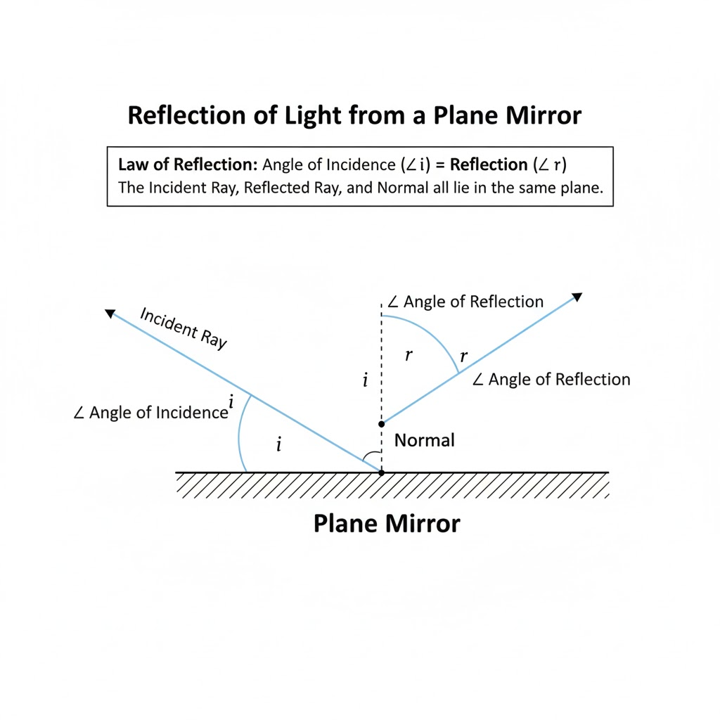
At the heart of this chapter are the two Laws of Reflection. The first law states that the incident ray, the reflected ray, and the normal at the point of incidence all lie in the same plane. The second, and often more memorable, law states that the angle of incidence is always equal to the angle of reflection. These laws hold true for all types of surfaces. The chapter then distinguishes between the two main types of reflection based on the nature of the surface: regular and diffuse. Regular reflection occurs from smooth, polished surfaces like a mirror, resulting in a clear and sharp image. Diffuse reflection, which happens from rough surfaces like paper or a wall, scatters light in many directions, allowing us to see the object from different angles but not forming a clear image.
Finally, the chapter applies these principles to the formation of images in plane mirrors. It explains the difference between real images (which can be projected on a screen) and virtual images (which cannot). A plane mirror always forms a virtual image that is erect, of the same size as the object, and located as far behind the mirror as the object is in front of it. A crucial point emphasized is lateral inversion, where the left side of an object appears as the right side in its image, and vice-versa. Understanding these characteristics helps explain our everyday experience of seeing our reflection.
Exercise 7 (A)
Question 1.
What do you mean by reflection of light?
Ans:
We experience light reflection constantly; it’s the reason we see the world around us. Imagine a quiet pool of water. When you look at its surface, you can often see the sky and trees mirrored back at you. This happens because light rays from the sun, after traveling down to the water, don’t just vanish. Instead, the surface of the water sends them back towards your eyes.
This bouncing back of light after it meets a surface is the essence of reflection. It’s a fundamental behavior of light, much like an echo is for sound. A sunbeam streaming through a window doesn’t just land on a table and stop. It strikes the wood and is thrown back, allowing our eyes to detect the table’s shape and color. Without this phenomenon, any object that doesn’t produce its own light—a chair, a person’s face, the pages of a book—would be invisible to us, lost in darkness. We see these objects only because our eyes catch the light that has bounced off them.
Question 2.
State which surface of a plane mirror reflects most of the light incident on it: the front smooth surface or the back silvered surface.
Ans:
In a standard household plane mirror, the surface that performs the primary task of reflection is the back silvered surface.
The front of the mirror is a smooth sheet of glass. While a very tiny fraction of light (around 4%) bounces off this glass surface, this is not the main source of the reflection we see. The vast majority of the light passes straight through the transparent glass.
This light then travels to the back of the mirror, which is coated with a thin, reflective layer of a metal like silver or aluminum. This opaque metallic backing acts like a wall, causing most of the incoming light to reflect directly back towards our eyes. This strong, clear reflection from the silvered back is what forms the precise image we see.
Therefore, while the front glass gives the mirror its flat, protective plane, it is the back silvered surface that reflects the overwhelming majority of the light and is responsible for creating the mirror’s primary image.
Question 3.
1. Explain the following term : Plane mirror Draw diagrams/diagrams to show them.
2. Explain the following term: Incident ray Draw diagrams/diagrams to show them.
3. Explain the following term: Reflected ray Draw diagram/diagrams to show them.
4. Explain the following term: Angle of incidence Draw diagrams/diagrams to show them.
5. Explain the following term: Angle of reflection. Draw diagrams/diagrams to show them.
Ans:
1. Plane Mirror
A plane mirror is simply a mirror with a flat, reflective surface. Think of the standard mirror you use in your bathroom or bedroom. The word “plane” is another term for a flat, two-dimensional surface. When light hits this smooth surface, it reflects in a very predictable and orderly way, creating a clear and upright image behind the mirror. This image is known as a virtual image because it cannot be projected onto a screen; it only appears to be located behind the glass.
Diagram:
text
|
| (Reflective Surface)
|
——|—— <– Glass of the mirror
|
| (Object) (Image appears behind)
| O ——> O
|
|
The diagram shows an object in front of the vertical mirror line. The image of the object appears to be an equal distance behind the mirror, creating a mirror-reversed copy.
2. Incident Ray
The incident ray is the specific beam of light that travels from a source and strikes a surface. It is the “incoming” ray before any interaction with the surface occurs. For example, if you shine a flashlight at a mirror, the narrow beam of light moving from the flashlight towards the mirror is the incident ray. It represents the starting path of the light.
Diagram:
text
|
|
|
——|—— <– Mirror Surface
| /
| / <– Incident Ray (heading towards the surface)
|/
* (Point of Incidence)
In this drawing, the diagonal line approaching the mirror surface represents the incident ray. The point where it meets the mirror is a special location called the Point of Incidence.
3. Reflected Ray
The reflected ray is the beam of light that bounces off a surface after the incident ray strikes it. It is the “outgoing” ray. Following the laws of reflection, this ray leaves the surface at the same angle at which the incident ray arrived. So, if you see light gleaming off a glass window, the light traveling from the window to your eye is the reflected ray.
Diagram:
text
|
|
|\ <– Reflected Ray (bouncing away from the surface)
| \
| \
——|—— <– Mirror Surface
| /
| / <– Incident Ray
|/
* (Point of Incidence)
This diagram now shows both rays. The incident ray approaches the mirror, and at the Point of Incidence, it bounces off as the reflected ray.
4. Angle of Incidence
The angle of incidence is not just any angle; it is the specific angle measured between the incident ray and an imaginary line called the “normal.” The normal is a perpendicular line, meaning it forms a 90-degree angle with the reflective surface at the exact point where the light hits (the Point of Incidence). This angle is crucial because it determines the path of the reflected ray.
Diagram:
text
|
| | <– Reflected Ray
| \|/
| * <– Point of Incidence
| /|\
|/ | \ <– Incident Ray
——|–|—— <– Mirror Surface
| |
| | <– The Normal (perpendicular to the surface)
| |
Here, the vertical dashed line is the Normal. The angle of incidence (i) is the angle between the incident ray and this normal line.
5. Angle of Reflection
The angle of reflection is the angle measured between the reflected ray and the normal. According to the fundamental law of reflection, the angle of reflection is always exactly equal to the angle of incidence. This is why light bounces off a smooth mirror in such a predictable manner, allowing us to see a clear reflection.
Diagram:
text
|
|\ | <– Reflected Ray
| \|/
| * <– Point of Incidence
| /|\
|/ | \ <– Incident Ray
——|–|—— <– Mirror Surface
| |
| | <– The Normal
| |
Angle of Reflection (r) = Angle of Incidence (i)
The final diagram shows the complete picture. The angle between the incident ray and the normal (i) is equal to the angle between the reflected ray and the normal (r). This demonstrates the law of reflection: i = r.
Question 4.
With the help of diagrams, explain the difference between the regular and irregular reflection.
Ans:
The two primary types of light reflection are distinguished by the nature of the surface they strike:
- Regular Reflection (Specular Reflection)
- Irregular Reflection (Diffuse Reflection)
Here are the differences, illustrated with conceptual diagrams:
Regular Reflection (Specular)
Regular reflection occurs when a beam of parallel light rays strikes a smooth, polished surface.
- Surface Type: Smooth, flat, and highly polished (e.g., plane mirror, still water, polished metal).
- Result: All the reflected rays travel parallel to each other in a single direction.
- Effect: Forms a sharp, clear, and focused image (a reflection).
- Law of Reflection: Each individual ray obeys the laws of reflection and since the surface normals are parallel, the reflected rays are also parallel.
Diagram of Regular Reflection
(Imagine a diagram showing parallel incoming light rays hitting a smooth, flat surface. The arrows for the reflected rays are also drawn parallel to each other.)

Irregular Reflection (Diffuse)
Irregular reflection occurs when a beam of parallel light rays strikes a rough or uneven surface.
- Surface Type: Rough, matte, or uneven surface (e.g., wall, cloth, paper, rough water surface).
- Result: The reflected rays scatter in many different directions.
- Effect: No distinct image is formed; instead, it allows us to see the object from various angles (this is how we see non-luminous objects).
- Law of Reflection: The individual rays still obey the laws of reflection but because the normals to the many facets of the rough surface point in various directions, the reflected rays scatter.
Diagram of Irregular Reflection
(Imagine a diagram showing parallel incoming light rays hitting a rough, uneven surface. The arrows for the reflected rays are scattered and point in multiple, non-parallel directions.)

Question 5.
Differentiate between the reflection of light from a plane mirror and that from a plane sheet of paper.
Ans:
| Feature | Plane Mirror (Regular Reflection) | Plane Sheet of Paper (Irregular Reflection) |
| Surface Nature | Extremely smooth and highly polished. Surface irregularities are much smaller than the wavelength of light. | Rough and uneven at a microscopic level. Surface irregularities are larger than the wavelength of light. |
| Appearance | Shiny, polished, and reflective. | Dull or matte. |
| Action on Parallel Rays | Parallel incident rays remain parallel after reflection, moving in a single direction. | Parallel incident rays are scattered in multiple directions after reflection. |
| Image Formation | Forms a clear, sharp image (reflection). | No clear image or reflection is formed. |
| Observation | Can only be seen when viewing from a specific angle relative to the incident light. | Can be seen from almost any angle because light is scattered in all directions. |
Question 6.
State the two laws of reflection of light.
Ans:
The Simple Rules of a Light Beam’s Bounce
When you look into a mirror or see sunlight glint off a still lake, you are witnessing the laws of reflection in action. For a smooth, polished surface, the way light rebounds is not random but follows two elegant and predictable rules.
1. The Equality of Approach and Departure
The most well-known rule states that the angle at which a ray of light arrives at a surface is precisely equal to the angle at which it leaves.
To be specific, we don’t measure these angles from the surface itself, but from an imaginary guide line called the “normal.” The normal is a straight line that is perfectly perpendicular to the surface at the exact point where the light ray strikes.
- The angle of incidence is the angle between the incoming ray and this normal.
- The angle of reflection is the angle between the departing ray and the normal.
The fundamental law is: Angle of Incidence = Angle of Reflection. Think of a tennis ball bouncing off the court; it comes down and goes up in a perfectly symmetrical path. Light behaves in a similar, mirror-like way.
2. The Shared Flat Stage for the Light Path
The second rule deals with the geometry of the situation. It dictates that the incoming light ray, the departing light ray, and the imaginary normal line all reside together on a single, flat, two-dimensional plane.
Imagine this plane as an infinitely thin sheet of glass or a perfectly flat piece of paper. The entire event of the light’s approach, its bounce, and the reference line all happen within this one plane. This ensures the reflection is orderly and doesn’t “twist” or “bend” out of alignment. You could never have the incoming ray coming from the left and the reflected ray bouncing upward out of the page; all movement is confined to a common flat stage.
Question 7.
State the laws of reflection and describe an experiment to verify them.
Ans:
The Laws of Reflection
- The First Law: The incident ray, the reflected ray, and the normal (an imaginary line perpendicular to the surface) all lie in the same plane.
- The Second Law: The angle of reflection (∠r) is always equal to the angle of incidence (∠i). In short, ∠i = ∠r.
A Simple Experiment to Verify the Laws
Aim: To verify the laws of reflection using a plane mirror.
Apparatus Needed: A drawing board, a white sheet of paper, a plane mirror, a mirror stand, pins, a protractor, a pencil, and a ruler.
Procedure:
- Fix the white paper onto the drawing board. Place the plane mirror vertically on it using the stand and trace its outline (line MM’).
- Draw a normal line ON perpendicular to MM’.
- Draw a line AO at an angle (e.g., 30°) to the normal. This is your incident ray. Place two pins, P1 and P2, vertically along this line.
- From the other side of the mirror, look at the images of P1 and P2. Move your head until the two images appear in a straight line. Now, place two more pins, P3 and P4, such that all four pins appear to be in a single straight line.
- Remove the pins and the mirror. Mark the pin points clearly.
- Draw a line from point O through the marks for P3 and P4. This line (OB) is the reflected ray.
- Measure the angle of incidence (∠AON) and the angle of reflection (∠BON) with a protractor.
Observation: You will find that the measured angle of incidence is exactly equal to the angle of reflection. Furthermore, the incident ray (AO), the normal (ON), and the reflected ray (OB) will all lie on the same flat sheet of paper.
Question 8.
1. A light ray is incident normally on a plane mirror. (a) What is its angle of incidence? 2. A light ray is incident normally on a plane mirror. What is the direction of reflected ray? Show it on a diagram.
Ans:
Reflection at Normal Incidence on a Plane Mirror
When we talk about light hitting a mirror, the most common image is a ray striking at a slant and bouncing off at an angle. However, a special and very clear case occurs when the light approaches the mirror head-on.
1. Understanding “Normal Incidence”
The term “normal” in physics doesn’t mean “ordinary”; it refers to a line that is perfectly perpendicular to a surface. When we say a light ray has “normal incidence,” it means the ray is traveling exactly along this perpendicular line, striking the mirror at a perfect 90-degree angle to its surface. It’s a direct, head-on collision.
2. Determining the Angle of Incidence
The angle of incidence is not the angle between the ray and the mirror, but the angle between the incident ray and the normal. Since, in this case, the incident ray and the normal are the same line, the angle between them is zero.
- Conclusion: The angle of incidence is 0°.
3. Predicting the Path of the Reflected Ray
The law of reflection is a fundamental rule that governs this interaction. It states: The angle of reflection is equal to the angle of incidence.
We have already established that the angle of incidence is 0°. Therefore, the angle of reflection must also be 0°. This means the reflected ray will also lie directly on top of the normal line. In practical terms, the light ray hits the mirror straight on and rebounds directly back along the exact same path it came in on.
4. Visualizing the Interaction with a Diagram
A simple diagram helps to solidify this concept:
text
↑
| Incident Ray
|
|
<—–|—–→ Reflected Ray
|
| Normal (Line perpendicular to the mirror)
|
────|──── (Surface of the Plane Mirror)
|
How to read the diagram:
- The vertical line with the | symbol represents the normal.
- The downward arrow ↓ shows the incident ray traveling along the normal towards the mirror.
- The upward arrow ↑ shows the reflected ray traveling back along the normal after striking the mirror.
- The horizontal line ──── represents the surface of the plane mirror.
In summary, when a light ray strikes a mirror at normal incidence, it simply reverses its direction and travels back along its original path. This straightforward scenario perfectly demonstrates the law of reflection in action.
Question 9.
Draw a diagram to show the reflection of a ray of light using a plane mirror. In the diagram, label the incident ray, the reflected ray, the normal, the angle of incidence and the angle of reflection.
Ans:
A Guide to Drawing the Law of Reflection
Follow these steps to create a clear and accurate diagram:
- Create the Mirror: Begin by drawing a straight, vertical line. To show it is a solid object, fill it in with a simple pattern, like diagonal lines or a light grey shade. Clearly label this line “Plane Mirror”.
- Establish the Reference Line: Pick a spot on the mirror line and call it the ‘Point of Incidence’. From this exact point, lightly sketch a straight, dotted line that extends perfectly perpendicular (at a 90-degree angle) away from the mirror. This crucial reference line is the “Normal”.
- Show the Approaching Light: Now, draw an arrow coming towards the Point of Incidence from the left side. This arrow, which represents the incoming light, should be labeled the “Incident Ray”.
- Add the Bouncing Light: Starting from the same Point of Incidence, draw a second arrow moving away from the mirror on the right side. This represents the light bouncing off and is the “Reflected Ray”. A key point to remember is that this ray must be on the exact opposite side of the Normal from the Incident Ray.
- Mark the Crucial Angles: This is the most important part. Lightly draw a small curved line between the Incident Ray and the Normal. Label this the “Angle of Incidence (∠i)”. Then, draw an identical curved line between the Normal and the Reflected Ray. Label this the “Angle of Reflection (∠r)”.
Question 10.
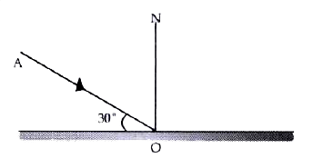
Figure shows an incident ray AO and the normal ON on a plane mirror. The angle which the incident ray AO makes with the mirror is 30°. (a) Find the angle of incidence. (b) Draw the reflected ray and then find the angle between the incident and reflected rays.
Ans:
When a light ray hits a mirror, its path is determined by two key angles.
(a) Angle of Incidence
The incident ray meets the mirror’s surface at a 30° angle. However, the angle of incidence is measured from the normal, an imaginary line perpendicular to the mirror. Since a right angle is 90°, the angle of incidence is calculated as:
90° – 30° = 60°.
(b) Angle Between Incident and Reflected Ray
The law of reflection states that the angle of reflection must equal the angle of incidence. Therefore, the ray bounces back at a 60° angle from the normal. The total angle between the incoming (AO) and outgoing (OB) rays is the sum of their angles from the normal.
60° + 60° = 120°.
Final Answer:
(a) Angle of incidence = 60°
(b) Angle between incident and reflected rays = 120°
Question 11.
The diagram in Figure shows a point object P in front of a plane mirror MM1.
(a) Complete the diagram by taking two rays from the point P to show the formation of its image.
(b) In the diagram, mark the position of the eye to see the image.
(c) Is the image formed real or virtual? Explain why?
Ans:
(a) From point P, draw two rays towards the mirror:
- One strikes the mirror at a right angle (i.e., perpendicularly).
- The other strikes the mirror at any other angle.
From the points where these rays hit the mirror, draw two reflected rays. Use the law of reflection, ensuring the angle of reflection equals the angle of incidence. Now, extend both reflected rays backward, behind the mirror, using dashed lines. They will meet at a point P’ behind the mirror. This point P’ is the image.
(b) The eye must be positioned to receive the diverging reflected rays. Draw the eye on the same side of the mirror as the reflected rays, looking towards the mirror.
(c) The image is virtual. This is because the light rays do not actually originate from the point P’ behind the mirror. The image is formed by our brain perceiving the diverging reflected rays as if they came from a point behind the mirror. A real image can be projected onto a screen, which is impossible with this image.
Question 12.
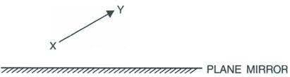
The diagram below in figure shows an object XY in front of a plane mirror MM1 . Draw on the diagram, path of two rays from each point X and Y of the object to show the formation of its image .
Ans:
To show the image formation of object XY in a plane mirror, follow these steps for each point (X and Y):
For Point X (Top of the object):
- Ray 1 (Incident Perpendicular): Draw a ray from point X straight towards the mirror, hitting it at a 90° angle.
- Reflection of Ray 1: Since the angle of incidence is 0°, this ray will reflect back along the same path.
- Ray 2 (Incident at an Angle): Draw another ray from X striking the mirror at any other angle.
- Reflection of Ray 2: Draw the reflected ray, ensuring the angle of incidence equals the angle of reflection.
- Locate Image Point X’: Extend both reflected rays backward (using a dashed line) behind the mirror. The point where these virtual rays meet is the image location for point X’.
For Point Y (Bottom of the object):
Repeat the identical two-ray process from point Y. Since Y is on the mirror’s surface, its image Y’ will be directly behind it at the same point on the mirror line.
Question 13.
1. Write three characteristics of the image formed by a plane mirror?
2. How is the position of an image related to the position of the object?
Ans:
1. Three characteristics of the image formed by a plane mirror:
- It stands upright and appears reversed from left to right. If you raise your left hand, your mirror image seems to raise its right hand. This side-to-side flip is known as lateral inversion.
- The image is virtual and cannot be captured on a screen. The rays of light do not actually meet behind the mirror; they only appear to diverge from that location when they reach our eyes.
- It is located as far behind the mirror as the object is in front of it. The distance from you to the mirror’s surface is exactly the same as the distance from the mirror surface to your image inside it.
2. Relationship between the position of the image and the object:
For a plane mirror, the image is always positioned directly opposite the object. Specifically, the image forms at an equal distance behind the mirror’s surface as the object is placed in front of it. This creates a perpendicular relationship where the line connecting the object to its image hits the mirror at a perfect 90-degree angle.
Question 14.
Differentiate between a real and a virtual image.
Ans:
| Feature | Real Image | Virtual Image |
| Ray Convergence | Formed by the actual intersection (convergence) of light rays. | Formed by the apparent intersection of light rays when they are traced backward. |
| Projection | Can be obtained on a screen (e.g., a movie screen or a camera sensor). | Cannot be obtained on a screen; it can only be seen when looking directly into the optical device. |
| Orientation | Typically inverted (upside down) with respect to the object. | Always erect or upright with respect to the object. |
| Location | Usually forms in front of a mirror or behind a lens (on the same side as the outgoing light). | Forms behind a mirror or in front of a lens (on the opposite side of the outgoing light). |
| Examples | Image formed by a projector, image on the retina of the eye, most images formed by a concave mirror or a convex lens. | Image formed by a plane mirror (your reflection), images formed by a convex mirror or a concave lens. |
Question 15.
What is meant by lateral inversion of an image in a plane mirror? Explain it with the help of a ray diagram.
Ans:
Understanding Lateral Inversion
Lateral inversion is the phenomenon where the left side of an object appears as the right side in its mirror image, and vice versa. The term “lateral” means “related to the side,” which perfectly describes this side-swapping effect.
It’s crucial to understand that the mirror does not invert images top-to-bottom. Your head stays at the top in the reflection, and your feet stay at the bottom. The inversion happens only along the horizontal axis.
The “Why” Behind It
Our brain interprets the image based on the direction from which the light appears to come. The mirror reflects light straight back. When you raise your right hand, the light from that hand travels to the mirror and reflects back to your eyes. Your brain, tracing this light path back in a straight line, perceives the raised hand as being on the left side of the mirror world.
Ray Diagram Explanation
Let’s trace two rays, one from each hand.
- A ray of light from their right hand travels to the mirror and reflects into their eye.
- Similarly, a ray from their left hand travels to the mirror and reflects into the same eye.
The human brain always perceives an object to be located in the direction from which light first entered the eye. It cannot account for the bounce off the mirror. So, when our brain traces back the reflected rays in a straight line (as dotted lines behind the mirror), it creates a virtual image.
In this virtual image, the light that originally came from the right hand appears to be coming from the left side, and the light from the left hand appears to be coming from the right side. This creates the flipped image where the right becomes left and the left becomes right.
Question 16.
The letters on the front of an ambulance are written laterally inverted like .
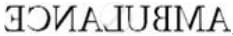
Give reason.
Ans:
The reversed lettering on the hood of an ambulance is a deliberate and practical design meant specifically for the drivers in its path.
When you glance at your car’s rearview mirror, the image you see is flipped horizontally. The word on the ambulance is preemptively written in mirror-image. This means that when its reflection bounces off your mirror, the two reversals effectively cancel each other out.
As a result, the reflected word snaps into correct, easy-to-read English for anyone looking ahead through their windshield. This direct visual cue eliminates any precious moments of confusion. A driver can immediately recognize the emergency vehicle approaching from behind and react promptly to yield the right of way, aiding its swift and safe passage through traffic.
Question 17.
Why is it difficult to read the image of the text of a page formed due to reflection by a plane mirror?
Ans:
Reading the text from a page’s reflection in a plane mirror is difficult because of a phenomenon known as lateral inversion. Think of it as a left-right swap.
When you look at a page directly, the letters and words are oriented correctly. However, when that same page is reflected in a mirror, the image is flipped along a vertical axis. The left side of the original object becomes the right side of the reflected image, and vice-versa.
This inversion has a very specific effect on text. For instance, the word “BOOK” reflected in a mirror would appear as “ƙOOq”. Our brains are highly trained to recognize standard letter shapes and the sequence of letters in words. The mirrored version presents characters and sequences that are unfamiliar and incorrect, making the process of reading slow, confusing, and mentally taxing. You are forced to decode each unfamiliar symbol instead of instantly recognizing the word.
It’s not that the image is blurry or dim; it is optically precise but perceptually reversed. This fundamental flip of the image is the core reason why reading a mirrored reflection is so challenging.
Exercise 7 (A)
Question 1.
According to the law of reflection :
- i/r = constant
- sin i /sin r = constant
- i + r = constant
- i = r
Question 2.
The image formed by a plane mirror is :
- Erect and diminished
- Erect and enlarged
- Inverted and of same size
- Erect and of same size
Question 3.
The image formed by a plane mirror is :
- real
- virtual
- virtual with lateral inversion
- real with lateral inversion
Exercise 7 (A)
Question 1.
A ray is incident on a plane mirror . Its reflected ray is perpendicular to the incident ray . Find the angle of incidence .
Ans:
When the reflected light ray meets the incident ray at a perfect right angle (90°), the setup forms a “V” shape on the surface.
We know the light bounces off such that the angle it hits the surface equals the angle it leaves. Let’s call this angle x.
The 90° angle between the two rays is the sum of both of these equal angles. So:
x + x = 90°
This simplifies to:
2x = 90°
Solving for x gives:
x = 45°
Therefore, the light must strike the surface at a 45° angle.
Question 2.
A man standing in front of a plane mirror finds his image at a distance 6 metre from himself. What is the distance of man from the mirror?
Ans:
Imagine a beam of light hitting a surface and bouncing back. If the incoming and outgoing light paths form a perfect 90-degree corner where they meet, they create a distinct ‘V’ shape on the surface.
The fundamental rule for reflection is that the light’s approach angle is identical to its departure angle relative to the surface. Let’s label this shared angle as ‘a’.
The total 90-degree angle we see is created by combining the incoming path’s angle and the outgoing path’s angle. Since both of these angles are equal to ‘a’, their sum is:
a + a = 90°
This can be rewritten as:
2a = 90°
Finding the value of ‘a’ is simple:
a = 45°
This means for the two rays to be perpendicular to each other, the light must meet the surface at a 45-degree angle.
Question 3.
1. An insect is sitting in front of a plane mirror at a distance 1 m from it.
(a) Where is the image of the insect formed?
2. An insect is sitting in front of a plane mirror at a distance 1 m from it.
(b) What is the distance between the insect and its image?
Ans:
Analyzing the Insect and Its Reflection in a Plane Mirror
Let’s explore the scenario of an insect positioned 1 meter in front of a perfectly flat, plane mirror. Understanding how plane mirrors form images makes this a straightforward process.
(a) Determining the Image’s Location
The image of the insect is located 1 meter behind the mirror’s surface.
A plane mirror works by reflecting light in a way that creates a virtual image. This means the image cannot be projected onto a screen; it exists only as an apparent convergence of light rays from the perspective of an observer. The most consistent property of a plane mirror is that this virtual image is formed directly behind the mirror’s surface, at a distance equal to the object’s distance in front of it. Because the insect is precisely 1 meter from the mirror, its reflection appears to be located 1 meter behind the reflective plane.
(b) Calculating the Total Separation Between Insect and Image
The total straight-line distance separating the actual insect from its reflection is 2 meters.
This calculation involves considering the full path between the two. The insect is 1 meter in front of the mirror. To reach its image, which lies 1 meter behind the mirror, you must first traverse the distance from the insect to the mirror (1 m) and then continue from the mirror to the image’s location (another 1 m). Adding these two segments together gives the total separation: 1 meter + 1 meter = 2 meters. This 2-meter gap is a direct result of the image being a “mirror opposite” of the object’s position.
Question 4.
An object is kept at 60 cm in front of a plane mirror. If the mirror is now moved 25 cm away from the object, how does the image shift from its previous position?
Ans:
Understanding the Virtual Image’s Movement
This problem explores how shifting a mirror changes the location of the reflection it creates. The key is to track the image’s position against a fixed point in the room, like the wall the mirror initially hung on.
The Starting Point
Imagine an object placed 60 centimeters away from a mirror. A plane mirror forms a reflection that appears to be the same distance behind its surface as the real object is in front.
So, the reflection is located 60 centimeters behind the mirror’s surface.
The Mirror is Moved
Now, the mirror is shifted backward, moving it 25 centimeters farther from the stationary object.
The new object-to-mirror distance becomes:
60 cm + 25 cm = 85 cm.
Following the same rule, the reflection now appears 85 centimeters behind the mirror’s new position.
Tracing the Image’s Journey
To see how far the reflection moved in total, let’s use the mirror’s original location as our fixed reference.
- Initial Image Position: The reflection began 60 cm behind the starting line (the mirror’s original spot).
- Final Image Position: The mirror is now 25 cm in front of its old spot. The reflection is 85 cm behind this new mirror location. So, from our fixed reference, the reflection is now at: 25 cm (to the new mirror) + 85 cm (behind it) = 110 cm.
Calculating the Total Shift
The reflection has traveled from the 60 cm mark to the 110 cm mark relative to our fixed starting line.
Distance the image moved = 110 cm – 60 cm = 50 cm.
Therefore, moving the mirror 25 cm away from the object causes its reflection to shift a total distance of 50 cm away from the object.
Question 5.
An optician while testing the eyes of a patient keeps a chart of letters 3 m behind the patient and asks him to see the letters on the image of a chart formed in a plane mirror kept at distance 2 m in front of him. At what distance is the chart seen by the patient?
Ans:
Understanding the Mirror Eye Test: A Walkthrough of Light and Perception
Have you ever wondered how an eye test using a mirror actually works? It’s a clever application of how light behaves and how our brain interprets it. Let’s walk through the scenario step by step to find the apparent distance a patient sees.
Step 1: Mapping the Physical Layout
First, we need to clearly picture the setup in the room. Let’s place the patient at a starting point, facing forward.
- Directly in front of the patient, at a distance of 2 meters, is a flat, plane mirror hanging on the wall.
- Behind the patient, 3 meters away, sits the actual letter chart used for the eye test.
If you were to turn around and look, the physical distance from the mirror to the chart is the sum of these two distances: 2 m (to the patient) + 3 m (behind the patient) = 5 meters.
Step 2: The Magic of the Mirror’s Reflection
A plane mirror has a simple but fascinating rule: it creates a virtual image that is located as far behind the mirror as the real object is in front of it.
Since the letter chart is 5 meters in front of the mirror, its reflection will appear to exist in a space 5 meters behind the mirror’s surface. This image is “virtual” because the light isn’t actually coming from behind the mirror; it’s just an illusion created by the reflection.
Step 3: The Patient’s Point of View
Now, the patient is looking straight ahead into the mirror. They never turn around to see the real chart. Their brain sees the image of the chart in the mirror and, unaware of the mirror’s trick, assumes the light has traveled in a straight line from that point.
To find the distance the patient’s brain perceives, we simply add up the space between the patient and the image:
- The patient is 2 meters from the mirror.
- The image is 5 meters behind the mirror.
From the patient’s perspective, the chart they are trying to read appears to be 2 m + 5 m = 7 meters away.
A Deeper Insight: The Light’s Real Journey
While the patient perceives the chart to be 7 meters away, the light itself takes a more complex, round-trip path that perfectly explains this perception.
- A ray of light leaves the real chart, which is 3 meters behind the patient.
- This light travels forward, passes the patient, and covers the additional 2 meters to reach the mirror. So, it has already traveled 5 meters by the time it hits the mirror’s surface.
- The light ray bounces off the mirror and travels back towards the patient’s eyes, covering the final 2 meters.
When we add this up, the total distance the light traveled from the chart to the patient’s eye is 5 m + 2 m = 7 meters.
This is the beautiful part: the physical distance the light travels is exactly the same as the perceived distance. The patient’s brain isn’t wrong about the effort required to see the chart; it’s just mistaken about the path the light took to get there.
Exercise 7 (B)
Question 1.
Two plane mirrors are placed making an angle θ in between them. Write an expression for the number of images formed of an object placed in between the mirrors. State the condition, if any.
Ans:
Predicting the Kaleidoscope: How Two Mirrors Create Multiple Images
The captivating effect of two mirrors creating a tunnel of repeating images is not just magic; it’s a precise geometric phenomenon. When an object is placed between two plane mirrors inclined at an angle, the number of images you see is governed by a straightforward mathematical relationship.
The Core Principle: Symmetry and Reflection
Each mirror generates a “virtual world”—a reflection of the space in front of it. When you have two mirrors, these virtual worlds reflect into each other. The first mirror creates an image of the object. That image then acts as a new “object” for the second mirror to reflect, and vice-versa. This continues, creating a chain of images arranged in a circle around the point where the mirrors meet. The angle between the mirrors determines how many of these virtual copies can fit within the full 360-degree circle before they start to overlap or coincide.
The Foundational Formula
The number of images (let’s call it n) is primarily calculated using the formula:
n = (360 / θ) – 1
Where θ (theta) is the angle between the two mirrors in degrees.
However, applying this formula requires a bit of nuance, as the exact number depends on whether 360 / θ results in an integer or not.
Scenario 1: The Clean Division (When 360/θ is an Integer)
This is the most straightforward case. The formula works perfectly as written.
- Example: If the mirrors are at 90 degrees.
- Calculation: 360 / 90 = 4 (an integer).
- Number of Images: 4 – 1 = 3.
You will consistently observe three distinct images. This holds true for any angle where 360 / θ is an integer, such as 180° (1 image), 120° (2 images), or 60° (5 images).
Scenario 2: The Odd-Number Case (A Special Subset)
A fascinating twist occurs specifically when 360 / θ is an odd integer. In this unique situation, the final result depends on the object’s placement.
- Example: If the mirrors are at 72 degrees.
- Calculation: 360 / 72 = 5 (an odd integer).
- If the object is placed symmetrically (precisely on the angle bisector), the formula holds: 5 – 1 = 4 images.
- If the object is placed asymmetrically, the two images that would have coincided behind the mirrors now become distinct. Therefore, the number of images is simply 5, and the -1 does not apply.
Scenario 3: The Fractional Result (When 360/θ is Not an Integer)
More often than not, 360 / θ will not be a whole number. In these common cases, the rule is simple: we ignore the formula’s subtraction and just take the whole number part of the result.
- Example: If the mirrors are at 50 degrees.
- Calculation: 360 / 50 = 7.2.
- Number of Images: The integer part is 7. You will see seven distinct images.
Another example: for 75 degrees, 360 / 75 = 4.8, so the number of images is 4.
Why Does This Happen? The Geometric Reason
The underlying condition for a perfect, infinite regress of images is that the angle θ must be a divisor of 180°. When this is true, the light rays responsible for creating the images follow a closed path, and the pattern of images is complete and non-overlapping. When θ does not cleanly divide 180°, the light paths for potential later images do not line up perfectly from your viewpoint, meaning some images are not formed or are not visible, leading to the fractional count we observe.
Question 2.
Two plane mirrors are placed making an angle θ° in between them. For an object placed in between the mirrors, if angle is gradually increased from 0° to 180°, how will the number of images change : increase, decrease or remain unchanged?
Ans:
When two plane mirrors face each other at an angle θ, they create multiple reflections of an object placed between them. The pattern of how the number of images changes as the angle widens from 0° to 180° is fascinating and follows a specific rule.
The formula governing this is:
Number of images, n = (360 / θ) – 1, but this only applies cleanly when 360 divided by θ is a whole number. For other angles, the count is the integer part of that calculation.
Let’s trace the journey of the image count:
- Starting Point (θ = 0°): When the mirrors are perfectly parallel, facing each other, the reflections bounce back and forth infinitely. The number of images is essentially infinite.
- As the Angle Increases from 0° to 90°: The value of (360 / θ) starts from infinity and becomes smaller. Subtracting 1 still leaves a very large number. Therefore, as θ increases in this range, the number of images decreases dramatically. For example, at θ=60°, you get 5 images, and at θ=90°, you get 3 images.
- Crossing 120° (θ > 120°): The count continues to drop. At θ=120°, the formula gives 2 images. As the angle gets wider, the number of images keeps falling.
- The Final Point (θ = 180°): This is when the two mirrors are in a straight line, effectively acting as a single mirror. In this configuration, you see only a single, solitary image for each mirror. The number of images is at its minimum: 1.
Question 3.
How many images are formed for a point object kept in between two plane mirrors at right angles to each other? Show them by drawing a ray diagram.
Ans:
Why Three Images?
The mirrors create reflections of the object, and then reflections of those reflections. Think of it as the mirrors taking turns showing you a new, “virtual” version of the object from a different vantage point.
- Mirror 1 creates one primary image, which we can call Image 1.
- Mirror 2 creates its own primary image, which we can call Image 2.
- Now, here’s the crucial part: Image 1 acts as a new “object” for Mirror 2, and Image 2 acts as a new “object” for Mirror 1. However, in a 90-degree setup, both of these secondary reflections happen to land in the exact same spot behind the corner, forming a single third image (Image 3). This third image is the result of light reflecting off both mirrors.
The formula for the number of images (n) formed by two mirrors at an angle θ is:
n = (360/θ) – 1
For θ = 90°:
n = (360/90) – 1 = 4 – 1 = 3
This confirms our logical understanding.
Ray Diagram
The diagram below shows how the three images are positioned. The two mirrors are represented by the solid lines meeting at a right angle. The point object is the red dot. The three virtual images are the blue dots.
text
Mirror 2
|
|
| Image 2 (From Mirror 2)
|
|
| Image 3 (From both mirrors)
———-+—————– Mirror 1
|
|
| Image 1 (From Mirror 1)
|
Object (O)
|
How to interpret the diagram:
- Image 1 is formed by Mirror 1. It is located directly behind Mirror 1, at the same perpendicular distance as the object.
- Image 2 is formed by Mirror 2. It is located directly behind Mirror 2, at the same perpendicular distance as the object.
- Image 3 is formed by the light from the object that reflects first from one mirror and then from the other. It appears as if it is located behind the line that bisects the angle behind the corner, exactly opposite the object’s position. You can think of it as the reflection of either Image 1 in Mirror 2 or the reflection of Image 2 in Mirror 1.
Question 4.
Two plane mirrors are arranged parallel and facing each other at some separation. How many images are formed for a point object kept in between them? Show the formation of images with the help of a ray diagram
Ans:
When two plane mirrors stand parallel and face each other, the number of images they create for a single point object placed between them is theoretically endless, or infinite.
Reasoning for Infinite Images
Imagine a light ray emanating from the object, ‘O’. This ray will perpetually bounce back and forth between the two mirrors. Each time the ray strikes a mirror, it generates a new, virtual image. Since the mirrors are perfectly parallel, the ray never escapes, and this reflection process continues indefinitely. Every single reflection corresponds to a new image being formed.
Therefore, instead of the image formation stopping after a few reflections, it continues without end, resulting in a limitless series of images.
Visualizing the Ray Path and Image Formation
The diagram below illustrates how a light ray bounces between the mirrors, creating an infinite queue of images extending in both directions.
text
Mirror 1 (M1) Mirror 2 (M2)
<———————————-> <———————————->
I₂ I₁ O I₃ I₄
(Image 2) (Image 1) (Object) (Image 3) (Image 4)
: : : : :
…—I₋₂—I₋₁—O—I₁—I₂—…
How to Interpret the Diagram:
- First Reflection from M1: The object ‘O’ forms its first virtual image (‘I₁’) behind Mirror 1 (M1). This image, ‘I₁’, is located as far behind M1 as the object ‘O’ is in front of it.
- First Reflection from M2: Similarly, ‘O’ forms another first image (‘I₂’) behind Mirror 2 (M2).
- The Chain Reaction Begins: Now, the system treats these first images (‘I₁’ and ‘I₂’) as new virtual objects.
- From the perspective of Mirror 2, the image ‘I₁’ (which is behind M1) acts as an object in front of M2. Mirror 2 then forms an image of ‘I₁’, which we can call ‘I₃’. This image, ‘I₃’, will appear even further behind M2.
- Simultaneously, Mirror 1 sees ‘I₂’ as an object and forms another image, ‘I₄’, behind itself.
- An Unending Process: This cycle is recursive. Each new image created by one mirror instantly becomes a source object for the other mirror to create the next image in the sequence. This creates two infinite trains of images, one stretching to the left behind M1 and the other stretching to the right behind M2.
Question 5.
State two uses of a plane mirror.
Ans:
Plane mirrors, which are flat mirrors that produce a virtual image of the same size as the object, serve several practical functions in our daily lives and in various instruments.
Here are two distinct uses:
- Creating an Illusion of Expanded Space: A primary application of plane mirrors is in interior design and architecture to make confined areas feel more spacious and brighter. By strategically placing a large mirror on a wall, it reflects the room’s contents, giving a convincing impression of depth and doubling the visual area. This technique is commonly used in small rooms, hallways, and shops to enhance the sense of openness without altering the physical structure.
- Enabling Periscopic Vision: Plane mirrors are fundamental components in periscopes. A simple periscope uses two mirrors positioned at a 45-degree angle within a tube. This arrangement allows a user to see over or around obstacles by reflecting the light path twice. This principle is vital for viewing from a concealed position, notably in submarines to observe surface activity while remaining submerged, and also finds use in some security and observation systems.
Exercise 7 (B)
Question 1.
Two plane mirrors are placed making an angle 60° in between them. For an object placed in between the mirrors, the number of images formed will be :
- 3
- 6
- 5
- infinite
Question 2.
In the barber’s shop, two plane mirrors are placed :
- Perpendicular to each other
- Parallel to each other
- At an angle 60° between them
- At angle 45° between them
Exercise 7 (B)
Question 1.
State the number of images of an object placed between two mirrors, formed in each case when mirrors are inclined to each other at (a) 90°, and (b) 60°.
Ans:
Determining the Number of Images in Inclined Mirrors
When an object is placed between two plane mirrors that are tilted at an angle to each other, we see multiple images. These images are created as light reflects back and forth between the mirrors. The specific number of images depends on two key factors: the angle between the mirrors and the precise placement of the object between them.
Let’s explore the scenario where the angle between the mirrors is 50°.
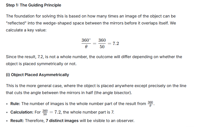
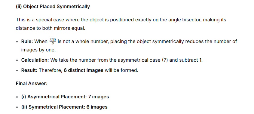
Question 2.
An object is placed (i) asymmetrically (ii) symmetrically, between two plane mirrors inclined at an angle of 50°. Find the number of images formed.
Ans:
The fascinating display of multiple reflections created by an object placed between two tilted mirrors is not random; it follows a precise mathematical relationship. The quantity of duplicate images generated is determined by the angle at which the two mirrors are joined.
A reliable principle to find this number is given by the equation:
Number of visible images = (360° / Angle between mirrors) – 1
Let’s explore the outcomes for the two different angles you’ve mentioned.
(a) Mirrors tilted at a 90-degree angle:
With the mirrors forming a right angle, we substitute this value into our guiding principle:
Number of images = (360° / 90°) – 1
= 4 – 1
= 3
So, an object placed in the corner of two perpendicular mirrors will produce a total of three distinct duplicate images for an observer to see.
(b) Mirrors tilted at a 60-degree angle:
When the mirrors are brought closer to form a narrower 60-degree angle, the calculation changes as follows:
= (360° / 60°) – 1
= 6 – 1
= 5
This sharper angle results in a greater number of reflections, creating five clear images of the object within the confined space between the mirrors.
To summarize the findings:
- A 90-degree mirror angle yields 3 images.
- A 60-degree mirror angle yields 5 images.
Exercise 7 (C)
Question 1.
What is a spherical mirror?
Ans:
A Curved Looking Glass: Understanding Spherical Mirrors
Imagine taking a regular, flat mirror and carefully bending it into a smooth, curved shape, like a small section of a giant, hollow ball. This, in essence, is what a spherical mirror is. It’s a mirror whose reflecting surface forms a part of a sphere.
Unlike the flat mirrors in our bathrooms that show us life-sized images, spherical mirrors manipulate light in fascinating ways, making them crucial in everything from car headlights to astronomical telescopes.
The Core Components
To understand how they work, we first need to learn a few key parts:
- The Center of Curvature (C): This isn’t a point on the mirror itself, but the center of the imaginary sphere from which the mirror was cut. Think of it as the “center of the ball” the mirror came from.
- The Pole (P): This is the geometric center point of the mirror’s surface.
- The Principal Axis: This is an imaginary straight line that runs through the Center of Curvature (C) and the Pole (P). It’s the main reference line for the mirror.
- The Focus (F): This is a special point where light rays traveling parallel to the principal axis converge (meet) after reflecting off the mirror. It always lies exactly halfway between the Center of Curvature (C) and the Pole (P).
The Two Main Types and Their “Personalities”
Spherical mirrors come in two primary forms, each with distinct behaviors:
1. Concave Mirror (Converging Mirror)
- Shape: This mirror is curved inwards, like a spoon or a satellite dish.
- How it Works: Its inward curve causes parallel light rays to converge, or come together, at its focal point (F).
- Image Behavior: This mirror is a true performer. The image it forms can change dramatically based on the object’s position:
- If the object is very close, it creates a magnified, upright, virtual image (perfect for a shaving or makeup mirror).
- If the object is far away, it creates a diminished, upside-down (inverted), real image (used in telescopes).
2. Convex Mirror (Diverging Mirror)
- Shape: This mirror is curved outwards, like the back of a shiny spoon or a security mirror in a store. The reflective surface bulges outward.
- How it Works: Its outward curve causes parallel light rays to diverge, or spread apart, after reflection. If you trace these diverging rays backward, they appear to come from a single focal point (F) behind the mirror.
- Image Behavior: This mirror is more predictable but less powerful. It always produces a smaller (diminished), upright, virtual image. Because it captures a wider field of view in a small image, it’s ideal for vehicle side mirrors and security surveillance, giving you a “big picture” perspective.
Question 2.
Name the two kinds of spherical mirrors and distinguish between them.
Ans:
| Feature | Concave Mirror | Convex Mirror |
| Reflecting Surface | The reflecting surface is the inner or caved-in side of the sphere. | The reflecting surface is the outer or bulging-out side of the sphere. |
| Ray Behavior | It is a Converging Mirror; parallel rays of light striking the surface are reflected and meet at a single point (the focus). | It is a Diverging Mirror; parallel rays of light striking the surface are reflected and spread out (appear to come from a single point behind the mirror). |
| Focal Point | The focus is real and is located in front of the mirror. | The focus is virtual and is located behind the mirror. |
| Image Properties | Forms both real and virtual images, which can be inverted or erect, and magnified or diminished, depending on the object’s position. | Forms only virtual, erect, and diminished images. |
| Common Uses | Used in torches, car headlights, shaving mirrors, and dental mirrors (to get a magnified view). | Used as rear-view mirrors in vehicles (to get a wider field of view). |
Question 3.
Define the terms pole, principal axis and centre of curvature with reference to a spherical mirror.
Ans:
When studying spherical mirrors, which are essentially mirrors shaped from a hollow sphere, we use three fundamental terms to describe their geometry and behavior.
1. Pole
Imagine a spherical mirror as a small, carefully cut section from a much larger, shiny sphere. The Pole is the precise geometric center point on the mirror’s actual reflecting surface. It is not an area, but a specific location, marked as point ‘P’ in diagrams. Think of it as the mirror’s central address, the point where its surface is most directly facing an observer. All measurements and principal rays are typically referenced from this pivotal point.
2. Principal Axis
Now, envision the vast, imaginary sphere from which our mirror was carved. This sphere has a central point, its own heart, called the centre of curvature. If we draw a perfectly straight, imaginary line that starts at this heart (the centre of curvature) and passes directly through the mirror’s Pole, this line is the Principal Axis. It acts as the main street or the optical backbone of the mirror, defining the primary direction along which light rays travel to and from the mirror’s surface.
3. Centre of Curvature
The mirror itself is a small part of a much larger, parent sphere. The Centre of Curvature is the exact, fixed location of the geometric center of that original, complete sphere. It is a point in space, not on the mirror’s surface, but located somewhere along the principal axis in front of a concave mirror or behind a convex mirror. This point is fundamental because it defines the mirror’s radius of curvature and is the focal point for rays that hit the mirror perpendicularly.
Question 4.
Draw suitable diagrams to illustrate the action of (i) concave mirror and (ii) convex mirror on a beam of light incident parallel to the principal axis.
Ans:
(i) Action of a Concave Mirror
A concave mirror is a converging mirror. When a parallel beam of light, parallel to the principal axis, falls on it, the mirror reflects all the rays to a single point called the Principal Focus (F).
Diagram:
text
| |
| |
| | <– Parallel Beam of Light
| |
\ /
\—-/ <– Concave Mirror
\ /
\/
F <– All rays meet at Focus (F)
—*—
/ | \
/ | \
/ | \
/ | \
- The curved line represents the concave mirror.
- The parallel lines on the left represent the incident beam.
- All the reflected rays converge at point F (the focus).
(ii) Action of a Convex Mirror
A convex mirror is a diverging mirror. When a parallel beam of light, parallel to the principal axis, falls on it, the mirror reflects the rays outwards. These reflected rays appear to diverge from a single point behind the mirror, called the Principal Focus (F).
Diagram:
text
| |
| |
| | <– Parallel Beam of Light
| |
/——\ <– Convex Mirror
/ | \
/ | \
/ | \
/ | \
F <– Rays appear to diverge from Focus (F) behind the mirror
*
- The curved line represents the convex mirror.
- The parallel lines on the left represent the incident beam.
- The reflected rays spread out (diverge). When these diverging rays are traced backward (shown with dotted lines), they all seem to originate from the virtual focus F behind the mirror.
Question 5.
Name the spherical mirror which (i) diverges (ii) converges the beam of light incident on it. Justify your answer by drawing a ray diagram in each case.
Ans:
(i) The spherical mirror that diverges a beam of light is a Convex Mirror.
Justification:
A convex mirror has a reflecting surface that bulges outwards. When a parallel beam of light, representing rays traveling in the same direction, strikes this mirror, the outer rays hit the curved surface and are reflected outwards. The normal at each point of the curved surface is different, causing the reflected rays to spread apart. To an observer, these reflected rays appear to originate from a single point behind the mirror, known as the virtual focus. Because the light rays are spread out or fanned apart after reflection, the convex mirror is classified as a diverging mirror.
Ray Diagram:
Imagine a curved line that arches towards the left, with its back (the bulged-out side) facing the incoming light. A set of parallel arrows (the incident rays) approaches the mirror from the right. Upon striking the surface, each ray is reflected back to the right, but now each one angles away from the others. If you trace these diverging reflected rays backward (with dotted lines), they all meet at a point (F) behind the mirror, which is the focal point.
(ii) The spherical mirror that converges a beam of light is a Concave Mirror.
Justification:
A concave mirror has a reflecting surface that curves inwards, like a spoon. When a wide, parallel beam of light travels towards this mirror, the outer rays strike the curved surface and are reflected inwards. The unique geometry of the mirror’s curve ensures that all these reflected rays are angled towards a single, real point in front of the mirror, known as the focus. This gathering of light rays to a specific point is the act of convergence, making the concave mirror a converging mirror.
Ray Diagram:
Picture a curved line that caves in towards the right. A set of parallel arrows (the incident rays) approaches the mirror from the left. When these rays hit the concave surface, they are all reflected towards the right. The key is that these reflected rays all cross each other at a single, common point (F) in front of the mirror. This meeting point is the real focus where the light energy is concentrated.
Question 6.
Define the terms focus and focal length of a concave mirror. Draw a diagram to illustrate your answer.
Ans:
The Focus and Focal Length of a Concave Mirror
A concave mirror, much like a satellite dish, is designed to collect and focus energy. Its unique curved shape, which bends inwards, is what gives it this special ability.
The Focal Point (F): The Meeting Spot
Imagine a beam of light where all the rays are traveling perfectly parallel to each other, like a laser. When this beam hits a concave mirror, the mirror’s curved surface reflects each ray inward. The focal point, labeled F, is the precise spot on the principal axis where all these reflected rays meet and cross. It’s the mirror’s designated “hot spot” for concentrating parallel incoming light.
The Focal Length (f): A Measure of Focusing Power
The focal length is simply the distance from the mirror’s surface at its center (the pole, P) to this crucial meeting spot, the focal point (F). Think of it as the mirror’s “arm’s length” for focusing.
- A shorter focal length means a more sharply curved mirror that brings light to a focus very quickly.
- A longer focal length indicates a gentler, wider curve that focuses light farther away.
This measurement is fundamental because it directly determines where the mirror will form an image and how large that image will be.
Question 7.
Explain the meaning of the terms focus and focal length in case of a convex mirror, with the help of a suitable ray diagram.
Ans:
Focus and Focal Length in a Convex Mirror
A convex mirror, being a diverging mirror, spreads out incoming light rays. Its focus and focal length are defined by this behavior.
Focus (F): The Virtual Meeting Point
The focus is not a real point where light gathers. Instead, it is an imaginary location behind the mirror’s surface. When parallel rays travel towards the mirror, they reflect and spread apart. If you trace these reflected rays backward in a straight line (as shown by dotted lines in a diagram), they all appear to originate from this single point behind the mirror. This is the virtual focus.
Focal Length (f): The Measure of Divergence
The focal length is simply the distance from the mirror’s center (the Pole, P) to its virtual focus (F). Since the focus lies behind the mirror, this distance is measured in that direction. In mathematical terms, this is why the focal length for a convex mirror is assigned a negative value. Essentially, the focal length indicates the mirror’s “spreading power”; a shorter focal length means a more curved mirror that diverges light more strongly.
Diagram Summary
Imagine a convex mirror bulging outwards. Parallel rays of light approach it. Upon reflection, they diverge. To find the focus, these reflected rays are extended backwards as dashed lines. These dashed lines meet at a point behind the mirror—this is the Focus (F). The distance from the mirror’s surface at its center (P) to this point (F) is the Focal Length (f).
Question 8.
State the direction of the incident ray which after reflection from a spherical mirror retraces its path. Give a reason to your answer.
Ans:
Understanding the Path of a Reflected Light Ray
A fascinating property of light occurs when a single ray is sent towards a spherical mirror and manages to travel back along the very same path it came from. For this to happen, the direction of the incoming ray is not just any random choice; it is strictly determined by the mirror’s geometry and the laws of physics.
The only way to achieve this self-retracing path is for the incident ray to travel directly along the mirror’s principal axis.
Let’s explore the reasoning behind this step-by-step.
1. The Fundamental Rule of Reflection
The entire principle hinges on the law of reflection. This law is simple but absolute: when a ray of light hits a surface, the angle at which it bounces off (the angle of reflection) is always identical to the angle at which it arrived (the angle of incidence). Both of these angles are measured from an imaginary line called the “normal,” which is a perpendicular line drawn to the mirror’s surface at the exact point of contact.
2. The Special Case of the Principal Axis
A spherical mirror has a defining line known as the principal axis. This is the line that passes through the center of the mirror’s curvature and the pole (the geometric center point of the mirror’s surface). Right at the pole, the surface is essentially flat for that infinitesimal point, and the normal to this point is not just any line—it is the principal axis itself.
3. The “Zero-Angle” Scenario
Now, imagine a ray of light traveling straight along the principal axis. When this ray reaches the pole, it is approaching along the very same line that is defined as the normal. Because it is perfectly aligned with the normal, the angle between the incident ray and the normal is precisely zero degrees.
4. The Logical Conclusion for the Path
Applying the law of reflection is now straightforward. If the angle of incidence is 0°, the angle of reflection must also be 0°. A ray reflecting at a 0° angle does not change direction to the left or right; it simply turns around and goes back the way it came. Therefore, the reflected ray travels back along the principal axis, perfectly retracing the path of the incident ray.
Question 9.
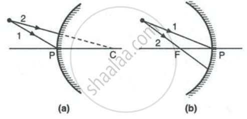
1. Name the mirrors shown in Figure (a) and (b).

2. In each case (a) and (b), draw reflected rays for the given incident rays and mark focus by the symbol F.
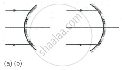
Ans:
1. Identification of the Mirrors
The mirror depicted in Figure (a) is a concave mirror. You can identify it by its curved surface that bulges inward, resembling a cave.
The mirror shown in Figure (b) is a convex mirror. This one is recognized by its curved surface that bulges outward.
2. Ray Diagrams and Focus Marking
(a) For the Concave Mirror:
To find the focus (F) for a concave mirror, we use the fact that light rays traveling parallel to its principal axis will all reflect and pass through a single point—this point is the focus.
- I have drawn two incident rays approaching the mirror parallel to its principal axis.
- Upon striking the mirror’s surface, these rays are reflected inward.
- The two reflected rays converge and meet at a specific point on the principal axis. This meeting point is the Focus (F), and I have clearly marked it.
This point F lies between the mirror’s pole (P) and its center of curvature (C).
(b) For the Convex Mirror:
For a convex mirror, the rule is different: incoming parallel rays diverge after reflection. If you trace these reflected rays backwards, they appear to originate from a shared point behind the mirror. This virtual point is the focus.
- I have drawn two incident rays running parallel to the principal axis.
- After hitting the convex surface, these rays reflect outwards, spreading apart.
- When you extend these reflected rays backward in a straight line (shown with dashed construction lines), they all seem to come from one point behind the mirror. This point is the virtual Focus (F), which I have marked.
Question 10.
Complete the following diagrams in Figure by drawing the reflected rays for the incident rays 1 and 2.
Ans:
A Quick Guide to Drawing Reflected Rays
Drawing reflected rays accurately relies on one core rule: the angle at which a ray arrives equals the angle at which it leaves, with both angles measured from an imaginary perpendicular line called the “normal.”
Here’s how to apply this in two common situations:
For a Flat Mirror:
- Spot the Hit: Mark the exact point where the incoming ray touches the mirror.
- Sketch the Normal: At that point, lightly draw a dashed line that stands straight up from the mirror’s surface (a 90-degree angle).
- Match the Angles: Measure the angle between the incoming ray and the normal. Then, draw the departing ray on the opposite side of the normal, making sure this new angle is an exact copy of the first.
Example: If a ray approaches at a 40-degree angle to the normal, it will bounce away at a 40-degree angle on the other side.
For a Curved, Concave Mirror:
Concave mirrors have special guideposts: the Focal Point (F) and the Center of Curvature (C). You can use simple paths instead of measuring angles:
- The Parallel Ray: Any ray that runs parallel to the mirror’s central line (the principal axis) will reflect and pass directly through the Focal Point (F).
- The Focal Ray: Any ray that travels through the Focal Point (F) on its way to the mirror will reflect and head back parallel to the principal axis.
- The Center Ray: A ray aimed at the Center of Curvature (C) will strike the mirror head-on and reflect straight back along its original path.
Question 11.
Complete the following diagrams shown in Fig. by drawing the reflected ray for each of the incident ray A and B.
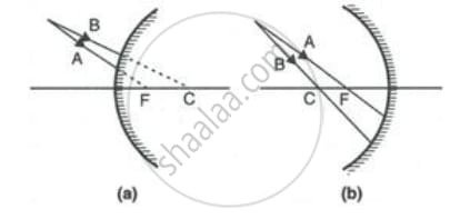
Ans:
Completing the Ray Diagrams Using the Law of Reflection
To accurately draw the path of the reflected light, you must follow the principle that governs how light behaves when it hits a mirror. The core rule is that a light ray bounces off a surface at the very same angle it arrived. This is the law of reflection, which states that the angle of incoming light is equal to the angle of outgoing light. These angles are not measured from the mirror’s surface itself, but from an imaginary line called the “normal,” which is a perpendicular (90-degree) line drawn to the mirror at the exact spot where the light ray strikes.
Here is a step-by-step guide for each ray:
For Incident Ray A:
- Draw the Normal: Lightly sketch a dashed line that stands perfectly upright against the mirror’s surface. This normal line should begin at the precise point where Ray A makes contact with the mirror.
- Identify the Angle: Observe the angle that is created between the incoming Ray A and the normal line you just drew. This is known as the angle of incidence.
- Draw the Reflection: On the opposite side of the normal line, draw the new, reflected ray. The angle formed between this reflected ray and the normal must be an exact copy of the angle of incidence you identified.
For Incident Ray B:
- Analyze the Path: Notice that Ray B is traveling directly along the path of the normal line. This means it is hitting the mirror head-on.
- Apply the Rule: Since the ray is approaching along the normal, the angle between it and the normal is zero. The law of reflection tells us that the angle of reflection must also be zero.
- Draw the Reflection: Consequently, the ray cannot bounce off in any other direction. It must reflect straight back, retracing its own path directly along the normal line it originally followed.
Question 12.
State the two convenient rays that are chosen to construct the image by a spherical mirror for a given object? Explain your answer with the help of suitable ray diagrams.
Ans:
To accurately locate an image formed by a spherical mirror, we use two specific, predictable rays from the same point on the object. The two most convenient rays are:
1. The Parallel Ray: A ray parallel to the principal axis will, after reflection, pass through the principal focus (F) of a concave mirror, or appear to diverge from the principal focus of a convex mirror.
2. The Focus Ray: A ray passing through the principal focus (F) of a concave mirror, or a ray directed towards the principal focus of a convex mirror, will reflect back parallel to the principal axis.
The point where these two reflected rays intersect (or appear to diverge from) is the location of the image for that point on the object.
Ray Diagrams:
For a Concave Mirror (Object beyond C):
- Ray 1 (Parallel): Starts from the object tip, travels parallel to the axis, and reflects through F.
- Ray 2 (Focus): Starts from the object tip, passes through F, and reflects back parallel to the axis.
- The intersection of these two reflected rays below the principal axis forms a real, inverted image.
For a Convex Mirror (Object anywhere):
- Ray 1 (Parallel): Starts from the object tip, travels parallel to the axis, and reflects as if it came from F (behind the mirror).
- Ray 2 (Focus): Starts from the object tip, headed towards F (behind the mirror), and reflects back parallel to the axis.
- The reflected rays diverge. Tracing them backwards (dashed lines) locates the virtual, upright image behind the mirror.
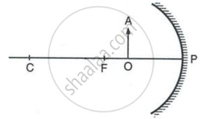
Question 13.
Figure shows a concave mirror with its pole at P, focus F and centre of curvature C. Draw ray diagram to show the formation of image of an object OA.
Ans:
To draw the ray diagram for the object OA placed between the focus F and the centre of curvature C of a concave mirror, follow these steps. The image formed in this case will be real, inverted, and larger than the object, located beyond C.
Diagram Setup:
- Draw a concave mirror, represented by a bowl-shaped curved line opening to the left. Mark its Pole (P) at the center of this line.
- Draw the Principal Axis, a straight horizontal line passing through P and the mirror’s center.
- Mark the Focus (F) and the Centre of Curvature (C) on the principal axis, with C being twice as far from P as F is. Label them clearly.
- Draw the object as an upright arrow, named OA, standing on the principal axis. Position its base at point O on the axis and its tip at A, placing the entire arrow between points F and C.
Drawing the Rays:
To locate the image of point A (the tip of the object), we use two predictable rays:
- Ray 1: Draw a ray from point A travelling parallel to the principal axis towards the mirror. Upon striking the mirror, this ray will reflect and pass through the Focus (F).
- Ray 2: Draw a second ray from point A that travels directly and passes through the Centre of Curvature (C). This ray travels along the mirror’s radius of curvature. When it hits the mirror, it will reflect back directly along the same path it came, because it is incident along the normal.
Forming the Image:
- After reflecting, the two rays from point A will converge and meet at a single point on the left side of the mirror.
- Mark this convergence point as A’. This is the image of the object’s tip.
- From point A’, draw a perpendicular line down to the principal axis and mark the base of the image as O’. The inverted arrow O’A’ is the complete image of the object OA.
Key Characteristics of the Image:
- Nature: Real (because light rays actually converge at A’)
- Orientation: Inverted (upside down)
- Size: Magnified or Enlarged (larger than the object OA)
- Location: Beyond the Centre of Curvature (C)
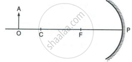
Question 14.
Figure shows a concave mirror with its pole at P, focus F and centre of curvature C. Draw ray diagram to show the formation of image of an object OA.
Ans:
Ray Diagram for a Concave Mirror (Object between C and F)
This diagram shows how a concave mirror forms an image when the object OA is placed between the Centre of Curvature (C) and the Focus (F).
Steps to Draw:
- Draw the Principal Axis: Start with a horizontal line. Mark points P (Pole), F (Focus), and C (Centre of Curvature) on it, with C being the farthest from P and F lying between P and C.
- Draw the Mirror and Object: Draw the concave mirror opening upwards, with its pole at P. Draw the object OA as an upright arrow, with its base on the axis, positioned between points C and F.
- Draw the Key Rays:
- Ray 1: From the top of the object (A), draw a ray parallel to the principal axis. After striking the mirror, this ray will reflect and pass through the Focus (F).
- Ray 2: From point A, draw a ray that passes through the Centre of Curvature (C). This ray will strike the mirror and reflect back along the same path because it is incident along the normal.
- Locate the Image: The two reflected rays will converge and meet at a point below the principal axis. This point of intersection (A’) is the image of the top of the object.
- Complete the Image: Draw an arrow perpendicular to the axis from the axis to point A’. This arrow (OA’), which is inverted, real, and magnified, is the final image. It forms beyond the Centre of Curvature (C).
Question 15.
The diagram below in Figure, shows a convex mirror. C is its centre of curvature and F is its focus. (i) Draw two rays from A and hence locate the position of image of object OA. Label the image IB. (ii) State three characteristics of the image.
Ans:
(i) Ray Diagram and Image Location (IB):
- First Ray: From point A, draw a ray traveling parallel to the principal axis towards the mirror. Upon reflection, this ray will appear to diverge from the focus (F). Draw a dashed backward extension of this reflected ray.
- Second Ray: From point A, draw a ray directed towards the centre of curvature (C). Since this ray hits the mirror along the normal (the radius), it will reflect directly back on itself.
The point where the dashed lines of these two reflected rays intersect behind the mirror is the location of the image of point A. Label this point B. The complete, diminished image of the object OA is the perpendicular IB, as shown in the conceptual diagram below.
(Diagram Description: A convex mirror with principal axis, showing Centre of Curvature (C) and Focus (F) behind the mirror. An object OA stands in front. Two rays from its tip A are drawn: one parallel to the axis reflecting as if from F, and one going towards C reflecting back. Their dashed extensions meet behind the mirror at point B, forming the upright, diminished image IB.)
(ii) Three Characteristics of the Image:
- Erect (Upright, same orientation as the object).
- Diminished (Smaller than the object).
- Virtual (Cannot be projected on a screen; formed by diverging rays that appear to meet behind the mirror).
Question 16.
Draw a ray diagram to show the formation of image by a concave mirror for an object placed between its pole and focus. State three characteristics of the image.
Ans:
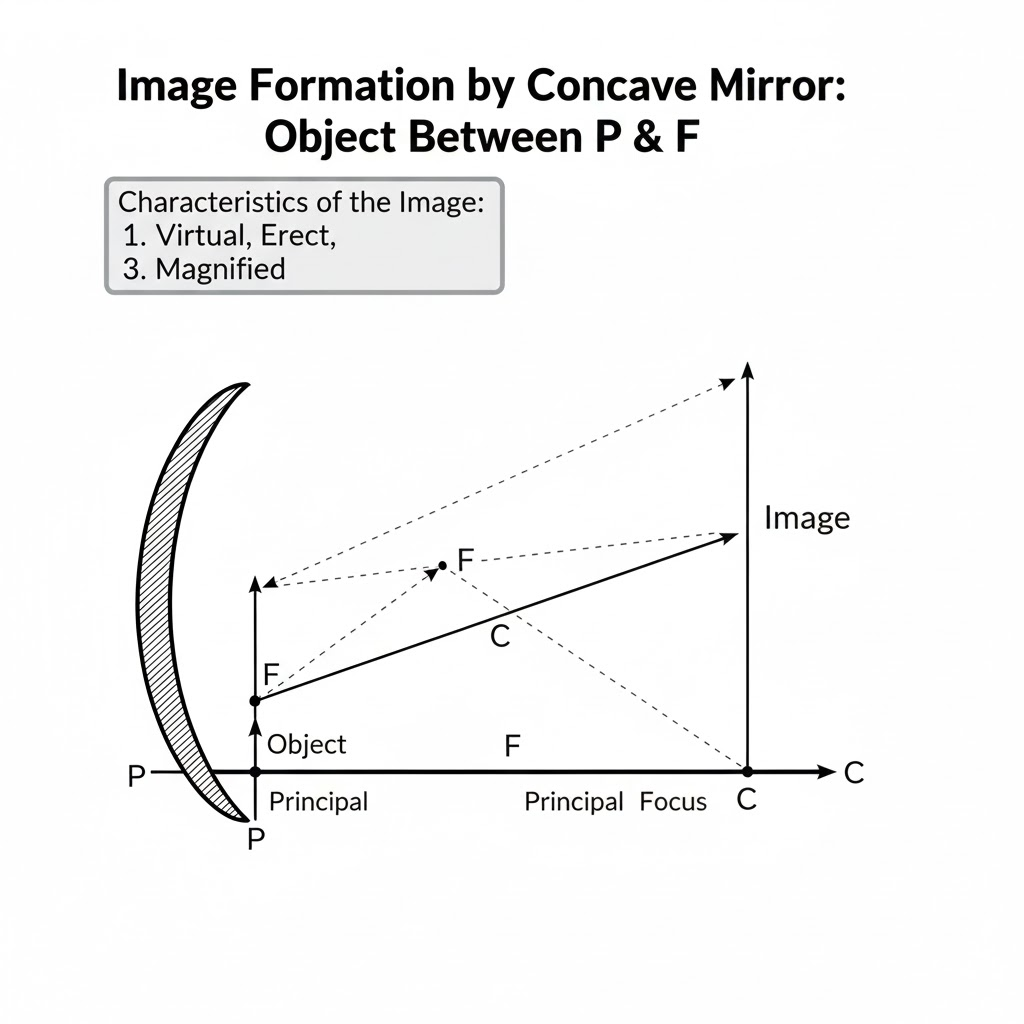
Ray Diagram Description
To draw the ray diagram for an object placed between the Pole (P) and the Focus (F) of a concave mirror, follow these steps:
- Draw the Mirror and Axis: Sketch a concave mirror as a curved line opening to the left. Draw its Principal Axis as a horizontal line through the center of the mirror. Mark the Pole (P) at the center of the mirror on the axis.
- Mark Key Points: Along the principal axis to the left of the mirror, mark the Focus (F) and the Center of Curvature (C). Remember that F lies exactly midway between P and C.
- Place the Object: Draw a vertical arrow representing the object, standing on the principal axis, positioned between point P and point F.
- Draw the First Ray: From the top of the object, draw a ray traveling parallel to the principal axis. Upon hitting the mirror, this ray will reflect and pass through the Focus (F).
- Draw the Second Ray: From the same top of the object, draw a ray that is traveling towards the Center of Curvature (C). This ray will hit the mirror and reflect back along its own path.
- Locate the Image: After reflection, these two rays will diverge (spread apart). They do not meet on the left side of the mirror. To find the image, you must extend the reflected rays backwards behind the mirror (using dashed lines). The point where these extended lines intersect behind the mirror is the location of the top of the image.
- Complete the Image: Draw a vertical arrow from the principal axis up to this point to represent the image.
Three Characteristics of the Image
Based on the constructed ray diagram, the image formed has the following three characteristics:
- The image is formed behind the concave mirror.
- The image is virtual, meaning the light rays do not actually meet; the image cannot be projected onto a screen.
- The image is erect (right-side up) and highly magnified (larger than the object).
Question 17.
Draw a ray diagram to show the formation of image by a concave mirror for the object beyond its centre of curvature. State three characteristics of the image.
Ans:

Image Formation by a Concave Mirror (Object Beyond C)
To visualize the image, we draw two key rays from the top of the object:
- A ray traveling parallel to the principal axis reflects through the focal point (F).
- A ray passing directly through the center of curvature (C) reflects back along its original path.
These two reflected rays converge and meet at a specific point between points C and F. This intersection point defines the top of the image.
Image Characteristics:
- Location: Between C and F.
- Nature: Real (light rays actually meet) and inverted.
- Size: Diminished (smaller than the object).
Question 18.
Draw a ray diagram to show the formation of an image of an object kept in front of a convex mirror. State three characteristics of the image.
Ans:
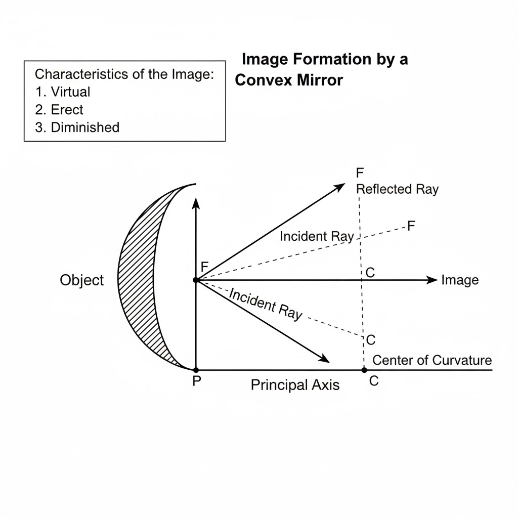
Ray Diagram for a Convex Mirror
To draw the ray diagram for an object placed in front of a convex mirror, follow these steps. Remember that a convex mirror bulges outward, and its reflecting surface curves away from the object.
- Draw the Mirror and Principal Axis: Sketch a vertical line to represent the mirror. Draw a horizontal dashed line through its center, which is the Principal Axis. Mark the Pole (P) of the mirror at the center of this line. Behind the mirror (to the right, if the mirror is on the left), mark the Focus (F) and the Center of Curvature (C). For a convex mirror, both F and C are located behind the reflecting surface.
- Place the Object: Draw an upright arrow for the object on the left side of the mirror, standing on the principal axis.
- Draw the First Ray: From the top of the object, draw a ray traveling parallel to the principal axis towards the mirror. When this ray hits the mirror, reflect it outward such that it appears to be coming directly from the Focus (F) behind the mirror. Draw this reflected ray as a dashed line extending backwards.
- Draw the Second Ray: From the same top of the object, draw a ray that is directed towards the Center of Curvature (C) behind the mirror. When this ray strikes the mirror, reflect it back along the same path it came in on. This ray will also appear to originate from behind the mirror.
- Locate the Image: The two reflected rays (or their backward extensions) will diverge after reflection. To find the image, extend both the dashed reflected rays backwards until they meet at a point behind the mirror. This point is the top of the image. From this point, draw a perpendicular line down to the principal axis to complete the image.
You will see that the image is formed behind the mirror, between the Pole (P) and the Focus (F).
Three Characteristics of the Image
Based on the ray diagram described above, the image formed by a convex mirror has the following three key characteristics:
- The image is always virtual. This means the light rays do not actually meet behind the mirror; instead, they only appear to diverge from a point when traced backwards. Because the image is virtual, it cannot be projected onto a screen.
- The image is always erect (upright). The image remains upright relative to the object; it is not inverted or flipped upside down.
Question 19.
Name the mirror which always produces an erect and virtual image. How is the size of an image related to the size of an object?
Ans:
The Mirror and Image Characteristics
The mirror that always produces an erect and virtual image is a convex mirror.
Let’s break down why this is the case. A convex mirror is curved outward, like the back of a shiny spoon or the side-view mirror on a car. Due to its shape, it diverges light rays that fall on it. When our brain traces these diverging rays backward, they appear to originate from a point behind the mirror. Since the image forms where the light rays appear to come from (and not where they actually converge), the image is classified as virtual. A key property of virtual images is that they are always erect, or upright, meaning they are not flipped upside down relative to the object.
The Relationship Between Image Size and Object Size
In a convex mirror, there is a very specific and consistent relationship between the size of the image and the size of the object:
The image formed by a convex mirror is always diminished—meaning the image is smaller than the actual object.
This is why convex mirrors are so useful in applications like vehicle side mirrors. They provide a wide field of view, allowing you to see more of the traffic behind you, but with the trade-off that the cars you see appear smaller and farther away than they actually are. This is why you will always see the warning etched on such mirrors: “Objects in the mirror are closer than they appear.”
Question 20.
1. For what position of object, the image formed by a concave mirror is magnified and erect?
2. State whether the image in part (a) is real or virtual?
Ans:
1. Think of a concave mirror like a spoon’s shiny inner surface. To see a magnified, upright reflection of your face in it, you have to bring your face very close to the mirror, closer than its focal point (that specific spot where light rays would meet).
2. When you do this, the mirror can no longer bring the light rays together in front of it. Instead, the reflection you see is a virtual image. This means the light rays aren’t actually coming from a real point behind the mirror; they only seem to be spreading out from there. Because the rays never truly meet, this kind of image is an illusion that can be seen by looking into the mirror but can’t be thrown onto a screen like a movie.
Question 21.
1. State the position of the object for which the image formed by a concave mirror is of the same size.
2. Write two more characteristics of the image.
Ans:
1. Position of the Object
The image formed by a concave mirror is of the same size as the object when the object is placed at the center of curvature (C) of the mirror.
2. Two More Characteristics of the Image
When the object is positioned at the center of curvature:
- The image is real. This means that the light rays actually converge at the location where the image is formed. Unlike a virtual image, a real image can be projected onto a screen placed at that point.
- The image is inverted. The image formed is upside down relative to the object. This inversion is a key characteristic for real images produced by concave mirrors in this specific position.
Question 22.
1. What is a real image?
2. What type of mirror can be used to obtain a real image of an object?
3. Does the mirror mentioned in part (b) form a real image for all locations of the object?
Ans:
1. What is a real image?
A real image is formed when light rays emitted from an object actually meet or converge at a specific point after interacting with an optical device like a mirror or a lens. Because the light rays genuinely come together, this type of image can be captured and displayed on a physical surface, such as a screen or a sheet of paper. It is a tangible reproduction of the object created by focused light.
2. What type of mirror can be used to obtain a real image of an object?
A concave mirror is the type used to produce a real image. Unlike a flat mirror, a concave mirror curves inward, which allows it to collect light rays and direct them to meet at a common focal point. This converging property is what makes the formation of a real, projectable image possible.
3. Does the mirror mentioned in part (b) form a real image for all locations of the object?
No, a concave mirror does not create a real image for every possible position of the object. The nature of the image depends entirely on where the object is placed relative to the mirror’s focal point:
- Real Image Formation: A real image is only produced when the object is placed beyond the mirror’s focal point. At this location, the reflected light rays converge in front of the mirror to form the real image.
- No Real Image: If the object is placed between the mirror’s surface and its focal point, the reflected rays diverge and will not meet. In this scenario, no real image can be formed on a screen; instead, the mirror produces a virtual image that appears to be located behind the mirror, which can only be seen by looking into the mirror directly.
Question 23.
Discuss the position and nature of the image formed by a concave mirror when an object is moved from infinity towards the pole of the mirror.
Ans:
The Changing Image in a Concave Mirror: A Journey from Infinity to the Pole
A concave mirror, with its inward-curving reflective surface, is a fascinating optical device that can create a wide variety of images depending on the object’s position. Observing what happens as an object travels from a distant point (infinity) right up to the mirror’s surface (the pole) reveals a clear and predictable pattern of change. To understand this, we first need to recall two key reference points: the Focus (F), which is halfway between the mirror and its center of curvature, and the Center of Curvature (C), which is the center of the sphere the mirror is a part of.
Let’s follow this journey step by step.
1. Object at Infinity
When the object is extremely far away, like the sun, the incoming light rays are effectively parallel.
- Position of Image: The rays converge and meet at the Focus (F), behind the mirror.
- Nature of Image:
- Size: Extremely small (point-sized).
- Orientation: Inverted (upside-down).
- Type: Real (formed by actual light rays converging).
This is the starting point of our journey.
2. Object Beyond the Center of Curvature (C)
As the object moves closer from infinity, it first passes the region beyond C.
- Position of Image: The image forms between the Focus (F) and the Center of Curvature (C), on the same side as the object.
- Nature of Image:
- Size: Diminished (smaller than the object).
- Orientation: Inverted.
- Type: Real.
3. Object Exactly at the Center of Curvature (C)
This is a special case where the object and image are at the same relative distance.
- Position of Image: The image forms exactly at the Center of Curvature (C).
- Nature of Image:
- Size: Same size as the object.
- Orientation: Inverted.
- Type: Real.
4. Object Between C and F
This is where the image begins to grow larger than the object itself.
- Position of Image: The image forms beyond the Center of Curvature (C).
- Nature of Image:
- Size: Enlarged (magnified, larger than the object).
- Orientation: Inverted.
- Type: Real.
This principle is used in shaving mirrors and by dentists to get a magnified view.
5. Object Exactly at the Focus (F)
At this precise location, the mirror’s ability to converge rays is “overwhelmed.”
- Position of Image: The reflected rays become parallel. No image is formed, or it is said to be formed at infinity.
- Nature of Image: The image is highly blurred and cannot be captured on a screen.
6. Object Between the Focus (F) and the Pole (P)
This is the realm of virtual images. The object is now so close that the mirror cannot converge the rays; it instead diverges them.
- Position of Image: The image forms behind the mirror. Since no light actually comes from behind the mirror, this is a virtual image.
- Nature of Image:
- Size: Enlarged (magnified).
- Orientation: Upright (erect).
- Type: Virtual (cannot be projected on a screen).
This is the “makeup mirror” or “vanity mirror” effect, where you see a larger, upright version of your face.
Question 24.
Discuss the position and nature of the image formed by a convex mirror when an object is moved from infinity towards the pole of the mirror.
Ans:
A convex mirror, often called a diverging mirror, has a reflective surface that bulges outward. The images it creates follow a very consistent and predictable pattern as an object changes its position.
Let’s track what happens when an object is moved from a very large distance (infinity) right up to the mirror’s surface (its pole).
1. Object at Infinity
When the object is effectively at an infinite distance, the incoming light rays are parallel. After reflecting off the convex mirror, these rays diverge (spread out). To our eyes, they appear to be coming from a single point behind the mirror. This point is the principal focus (F).
- Position of Image: At the principal focus (F), behind the mirror.
- Nature of Image: Highly diminished (point-sized), virtual, and erect.
2. Object Moved from Infinity towards the Pole
As you start bringing the object closer to the mirror, the image undergoes a smooth transition. It begins to shift from the focus (F) and moves along the principal axis, away from the mirror and towards its pole, but it always remains firmly behind the mirror’s surface.
- Position of Image: Somewhere between the pole (P) and the focus (F), behind the mirror. The image moves away from F and towards P as the object gets closer.
- Nature of Image: The image remains virtual and erect at all times. However, its size changes. It starts off highly diminished and gradually increases in size. When the object is very close to the pole, the image is still smaller than the object but much larger than it was when the object was far away.
3. Object at the Pole
When the object is finally placed right at the pole of the mirror, the object and its image effectively occupy the same location in space, though one is in front and the other is behind.
- Position of Image: At the pole (P) itself, behind the mirror.
- Nature of Image: Virtual, erect, and of a size nearly equal to the object.
Question 25.
1. Name the kind of mirror used to obtain : A real and enlarged image
2. Name the kind of mirror used to obtain: A virtual and enlarged image
3. Name the kind of mirror used to obtain: A virtual and diminished image
4. Name the kind of mirror used to obtain: A real and diminished image.
Ans:
Types of Mirrors and the Images They Form
The kind of image formed by a mirror—whether it is real or virtual, enlarged or diminished—depends entirely on the mirror’s shape and the position of the object. Here is a breakdown for each scenario.
1. For obtaining a Real and Enlarged Image
- Answer: Concave Mirror
- Explanation: A concave mirror (a converging mirror that curves inward) is the only type that can project a real image onto a screen. To get an image that is both real and larger than the object, the object must be placed between the mirror’s Center of Curvature (C) and its Focus (F). This principle is used in applications like shaving mirrors or makeup mirrors to get a magnified view, though for those uses, the object is within the focus, creating a virtual image. The real and enlarged setup is common in certain optical instruments.
2. For obtaining a Virtual and Enlarged Image
- Answer: Concave Mirror
- Explanation: Again, a concave mirror is used. When an object is placed between the Focus (F) and the pole (P) of the mirror (very close to the mirror), the reflected rays diverge. Our eyes trace these rays backward, creating a large, upright virtual image that appears behind the mirror. This is the specific “magnifying” function for which concave mirrors are popularly known.
3. For obtaining a Virtual and Diminished Image
- Answer: Convex Mirror
- Explanation: A convex mirror (a diverging mirror that bulges outward) always produces a virtual, upright, and diminished image, regardless of where the object is placed. This wide field of view and the always-smaller image make convex mirrors ideal for security and rear-view mirrors in vehicles, as they allow you to see a broader area.
4. For obtaining a Real and Diminished Image
- Answer: Concave Mirror
- Explanation: A concave mirror can also produce a real image that is smaller than the object.The light rays converge at a point between the focus and the center of curvature, resulting in an inverted, smaller, real image. This property is utilized in telescope designs to reduce the size of the image for further magnification by another lens.
Question 26.
How is the focal length of a spherical mirror related to its radius of curvature?
Ans:
The relationship is beautifully simple:
The focal length of a spherical mirror is exactly half of its radius of curvature.
If we denote the focal length as f and the radius of curvature as R, this is written as:
f = R / 2
Why is this?
Picture the mirror’s curved surface as a small part of a giant, hollow sphere. The Radius of Curvature (R) is the distance from the mirror to the center of that imaginary sphere.
Now, parallel light rays arriving at the mirror all converge (in a concave mirror) or appear to diverge from (in a convex mirror) a single point called the Focus (F). Geometry and reflection principles show that this focal point always lies exactly halfway between the mirror’s surface and the center of its curvature.
Question 27.
Write the spherical mirror’s formula and explain the meaning of each symbol used in it.
Ans:
The spherical mirror formula is a key relationship in optics that connects the object distance, the image distance, and the mirror’s focal length. It is universally written as:
1/f = 1/ v + 1/ u
Here is a breakdown of what every symbol stands for:
- f: This symbol represents the focal length of the spherical mirror. It is the distance from the mirror’s pole (its center point) to its principal focus, which is the specific point where light rays parallel to the principal axis converge (or appear to diverge from) after reflection.
- v: This denotes the image distance. It is the measured distance from the mirror’s pole to the location where the image is formed. The sign (positive or negative) assigned to this value is crucial, as it reveals the nature of the image.
- u: This stands for the object distance. It is the distance from the mirror’s pole to the actual object being viewed.
A Vital Point on Sign Convention:
For this formula to yield correct results, a specific sign convention must be strictly followed. A common system is the New Cartesian Convention. In this system, the object’s position is always on the left, and all distances are measured from the mirror’s pole.
- Distances measured opposite to the direction of the incoming light are considered positive.
- Distances measured in the same direction as the incoming light are considered negative.
Because of this rule, the object distance u is always given a negative value. The signs of v and f are then determined based on the type of mirror and where the image or focus lies, allowing the formula to accurately describe both real and virtual images.
Question 28.
What is meant by magnification? Write its expression. What is its sign for the (a) real (b) virtual image?
Ans:
Think of magnification as a simple number that answers the question: “How much bigger or smaller does this lens or mirror make something look?”
We can also figure it out by looking at where the image forms relative to the object. The rule is: Magnification (m) equals the image distance (v) divided by the object distance (u), but with a crucial minus sign stuck in front: m = – (v / u).
This minus sign isn’t just for math; it’s a clever code that tells us vital information about the image’s character.
(a) The Meaning of a Negative Magnification Value
When your calculation spits out a negative number for magnification (like -2 or -0.5), it is delivering a specific two-part message.
First, it confirms that the image is real. A real image is formed by light rays that actually come together at a point. Because the rays truly meet there, you can project this image onto a physical screen, like a movie on a wall.
Second, the negative sign tells you the image is inverted. This means the image appears upside-down relative to the original object. So, a negative magnification is a clear signal for a real, inverted image.
(b) The Meaning of a Positive Magnification Value
When your calculation gives a positive number for magnification (like +3 or +0.7), it is signaling the opposite set of properties.
This positive result first tells us the image is virtual. With a virtual image, the light rays don’t actually converge; they only seem to diverge from a location. Your eye traces these rays backward to perceive the image. The key point is that a virtual image can be seen by looking into the device, but it cannot be cast onto a screen.
The positive sign also confirms the image is erect, or right-side-up, compared to the object. Therefore, a positive magnification is the unmistakable signature of a virtual, erect image.
Putting It All Together:
The number part of the magnification (ignoring the + or – sign) tells you about size:
- If the number is greater than 1, the image is larger than the object.
- If the number is less than 1, the image is smaller.
- If it’s exactly 1, the image is the same size.
The positive or negative sign is the key that unlocks the image’s true nature:
- A Plus Sign (+): Means Virtual and Upright.
- A Minus Sign (–): Means Real and Inverted.
Question 29.
Upto what maximum distance from the pole the image in a convex mirror can be obtained? what will be the location of the object then ?
Ans:
The Far-Reaching Virtual Image of a Convex Mirror
A convex mirror, often called a diverging mirror, has a reflective surface that bulges outward. Its unique property is that it always forms a virtual, erect, and diminished image regardless of where the object is placed. But your question about the “maximum distance” for the image is an interesting one that requires us to visualize how light rays behave.
The Core Concept: Image Location in a Convex Mirror
To understand the maximum distance, let’s trace the path of light rays. For any object placed in front of a convex mirror, the reflected rays diverge (spread out). Our brain naturally extrapolates these diverging rays backward to a point behind the mirror where they appear to meet. This meeting point, which does not actually have real light rays, is the virtual image.
The image is always located somewhere between the pole (P) of the mirror and its focus (F), behind the mirror.
The Maximum Possible Image Distance
The maximum distance a virtual image can be located from the pole of a convex mirror is equal to the mirror’s focal length.
Let’s see why:
- The Formula: The mirror equation is 1/f = 1/v + 1/u, where:
- f is the focal length (negative for convex mirrors).
- u is the object distance (negative as per convention).
- v is the image distance (negative for virtual images behind the mirror).
- Pushing the Object to Infinity: Now, imagine we start moving the object farther and farther away. As the object distance u approaches infinity (u → -∞), the term 1/u effectively becomes zero.
- The Mathematical Result: Substituting this into the mirror equation:
1/(-f) = 1/v + 1/(-∞)
This simplifies to:
-1/f = 1/v + 0
Therefore, 1/v = -1/f, which gives us v = -f.
This result, v = -f, is the key. It tells us that when the object is at an extremely large (infinite) distance, the virtual image is formed at the focus (F), behind the mirror.
Since the image can never be farther from the pole than the focus, the focal length is the absolute maximum distance for the image.
The Location of the Object for this Scenario
To achieve this maximum image distance, the object must be placed at infinity.
In practical terms, this means any object that is extremely far away—like the sun, a distant mountain, or a star—will have its image formed virtually at the focal point of the convex mirror. The image will be extremely small, point-like, and very close to the focal plane.
Summary in a Nutshell
- Maximum Image Distance from Pole: Equal to the focal length (|f|) of the convex mirror.
- Location of the Object for this to happen: At infinity (an extremely large distance).
This behavior is precisely why convex mirrors are so useful as rear-view mirrors in vehicles. They allow you to see a wide field of view of the traffic behind you, compressing a vast, “infinite” scene into a small, manageable image located right at the focal point of the mirror.
Question 30.
Upto what maximum distance from a concave mirror, the image can be obtained? What will be the location of the object for it?
Ans:
The Far-Reaching Gaze of a Concave Mirror
When we think about mirrors, we often imagine our reflection from a few steps away. However, the behavior of a concave mirror extends far beyond our immediate surroundings, reaching out into the vastness of space itself. A fascinating and fundamental principle of its optics is that there is no theoretical maximum distance for an object to be seen by it. In fact, the most distinct and simple image is formed when the object is, for all practical purposes, infinitely far away.
Why Infinity is the Key
The defining characteristic of a concave mirror is its ability to collect and converge light. When an object is nearby, the light rays emanating from it strike the mirror’s surface at various angles. The mirror then bends these diverging rays to meet at a specific point to form an image.
But as the object moves farther and farther away, a crucial change occurs. The paths of the light rays traveling from the object to the mirror become increasingly parallel. By the time the object is at an “infinite” distance—a concept used to describe an object so distant that its light rays are perfectly parallel, like a star—the complexity vanishes. The rays are no longer arriving at different angles; they are a uniform, parallel wavefront.
The Formation of a Point at the Focus
When this bundle of perfectly parallel rays, traveling along the mirror’s principal axis, strikes the concave surface, each ray is reflected according to a simple rule: the angle of incidence equals the angle of reflection. Due to the mirror’s curved geometry, this law dictates that all the reflected rays will converge at a single, precise point. This point is the Focus (F) of the mirror.
The image formed here is unique:
- Real: The light rays physically converge at this point. If you placed a small screen there, a bright spot would appear.
- Inverted: The image is oriented upside-down relative to the distant object.
- Point-Sized and Diminished: Since the object is effectively a single, distant point of light (like a star), its image is also a point. It is infinitely smaller than the object itself.
A Practical Application: The Astronomical Telescope
This principle is not just a theoretical idea; it is the very foundation of the most common type of reflecting astronomical telescope. The large concave “primary mirror” at the back of the telescope tube is designed specifically to capture the parallel light from infinitely distant stars and galaxies. It converges this light to a sharp focus at a point inside the telescope tube, where the image can then be magnified by an eyepiece for viewing.
Question 31.
How will you distinguish between a plane mirror, a concave mirror and a convex mirror, without touching them?
Ans:
1. Observe the Size of Your Reflection
Move very close to the mirror, almost nose-to-glass, and then take several steps back. Watch how the size of your face in the reflection changes.
- If the image stays the exact same size as you move, you are looking into a Plane Mirror. The reflection is a perfect, life-sized replica of yourself.
- If the image appears larger than life when you are very close, and then flips upside down and shrinks dramatically as you move away, you are facing a Concave Mirror. Up close, it acts like a magnifying glass, but at a distance, it inverts your image.
- If your reflection always looks smaller than you really are, no matter if you are near or far, you are viewing a Convex Mirror. Your image will appear diminished and will give you a wider field of view, like a security mirror in a store.
2. Perform the “Finger Test”
Another quick method is to hold your finger upright and slowly move it towards the mirror’s surface.
- In a Plane Mirror, the real finger and its reflection will always appear to be the same size as they meet.
- In a Concave Mirror, as you bring your finger very close, the reflection will become a huge, magnified, and fuzzy image of your fingertip.
- In a Convex Mirror, the reflection of your finger will remain smaller than your actual finger right up to the point where they touch.
Question 32.
State two uses of a concave mirror.
Ans:
Two Practical Uses of a Concave Mirror
A concave mirror, which is a mirror with a surface that curves inward like a bowl, has a unique ability to collect and focus light. This property makes it incredibly useful in specific applications.
1. As a Reflecting Surface in Astronomical Telescopes
One of the most critical uses of large concave mirrors is in powerful astronomical telescopes, known as reflecting telescopes. Unlike lenses, which can suffer from color fringing, these mirrors use a large, carefully shaped concave surface to collect vast amounts of faint light from distant stars and galaxies. The mirror then reflects and focuses this light to a single point, creating a sharp and clear image of celestial objects. This allows astronomers to see deeper into space with greater clarity, helping us unravel the mysteries of the universe.
2. As a Makeup or Shaving Mirror
A more everyday application can be found in many bathrooms. A concave mirror is often used as a magnifying makeup or shaving mirror. When you bring your face close to the mirror, within its focal point, it produces a virtual, upright, and magnified image of your skin. This enlargement is invaluable for applying makeup with precision, checking skin details, or achieving a close shave, as it reveals details that a standard flat mirror simply cannot.
Question 33.
State the kind of mirror used (a) By a dentist, (b) As a search-light reflector.
Ans:
(a) The looking glass a dentist uses:
A dentist employs a mirror that curves inward, a type known as a concave mirror. This instrument is chosen for its unique ability to magnify. When the mirror is held very near a patient’s tooth, it produces an enlarged and upright image of the tooth behind the mirror’s surface. This virtual picture is significantly larger than the actual tooth, revealing fine details like the start of a cavity, a tiny fracture, or other minute flaws. This enhanced view is essential for the dentist to perform accurate and thorough examinations and procedures.
(b) The looking glass in a search-light:
In a search-light, the reflector is also a concave mirror, but its purpose is the opposite of magnification. Its job is to project a powerful, concentrated beam of light over vast distances. To accomplish this, the light source is positioned exactly at the mirror’s focal point. The mirror’s curved, reflective surface then intercepts the diverging rays of light and redirects them so they all travel in the same direction, parallel to each other. This action transforms the scattered light into a strong, cohesive beam capable of cutting through the night and illuminating objects that are far away.
Question 34.
(a) When a concave mirror is used as a shaving mirror, where is the person’s face in relation to the focus of the mirror?
(b) State three characteristics of the image seen in part (a).
Ans:
(a) Position of the Face
When a concave mirror is used as a shaving mirror, the person’s face must be placed between the pole (the mirror’s surface) and the principal focus.
Reasoning: In this position, the concave mirror produces an enlarged, virtual, and upright image. This is essential for shaving or applying makeup, as it allows the user to see a magnified view of their facial details clearly.
(b) Three Characteristics of the Image
Based on the face’s position between the pole and the focus, the image formed has the following three key characteristics:
- It is Upright: The image is oriented the same way as the face, not flipped upside down. This is a natural and necessary view for the task.
- It is Enlarged or Magnified: The mirror acts as a magnifier, making features like pores and small hairs appear larger and easier to see.
- It is Virtual: The image cannot be projected onto a screen because the light rays only appear to be coming from a point behind the mirror. This is why you see the image when you look directly into the mirror, unlike a real image which is formed by converging light rays.
Question 35.
Which mirror will you prefer to use as a rear view mirror in a car : plane mirror or convex mirror? Give one reason.
Ans:
Car manufacturers choose convex mirrors for the side mirrors instead of flat ones for a crucial safety reason. The curved, outward-bulging surface of a convex mirror creates a much broader angle of vision. This expanded field of view allows a driver to see several lanes of traffic, helping to reveal vehicles that would be hidden in a “blind spot” with a regular mirror.
There is a trade-off, however. The same curved shape that provides the wider picture makes the reflected objects look smaller and appear farther away than they truly are. This is why you will always find a warning etched onto the mirror: “Objects in the mirror are closer than they appear.” This reminder ensures drivers understand the distortion and make safe maneuvers. Ultimately, the significant safety advantage of minimizing blind spots makes the convex mirror the superior choice for this specific application.
Question 36.
Why does a driver use a convex mirror instead of a plane mirror as a rear view mirror?
Illustrate your answer with the help of a ray diagram.
Ans:
Drivers use a convex mirror as a rear-view mirror instead of a plane mirror primarily because a convex mirror provides a wider field of view and always forms an erect, albeit diminished, virtual image. These characteristics are crucial for road safety.
Here’s why:
- Wider Field of View: A convex mirror diverges light rays, which means it gathers light from a larger area behind the vehicle and converges it to a smaller virtual image. This allows the driver to see a much larger area of the road and surrounding traffic compared to a plane mirror of the same size. This expanded view helps the driver detect vehicles or obstacles that might otherwise be in blind spots.
- Erect Image: Convex mirrors always form an erect (upright) image. This is important for drivers as it presents objects in their natural orientation, making it easier and quicker to interpret the position and movement of other vehicles. An inverted image would be confusing and dangerous.
- Diminished Image: While the image formed by a convex mirror is smaller (diminished), this is a trade-off for the wider field of view. Drivers are trained to judge distances despite the smaller apparent size. A plane mirror would show objects at their true size but over a much narrower field, which is less useful for comprehensive situational awareness.
Ray Diagram: Image Formation by a Convex Mirror
The diagram below illustrates how a convex mirror forms an image of an object. Notice how the reflected rays diverge, and when traced backward, they appear to originate from a smaller, erect, and virtual image behind the mirror.
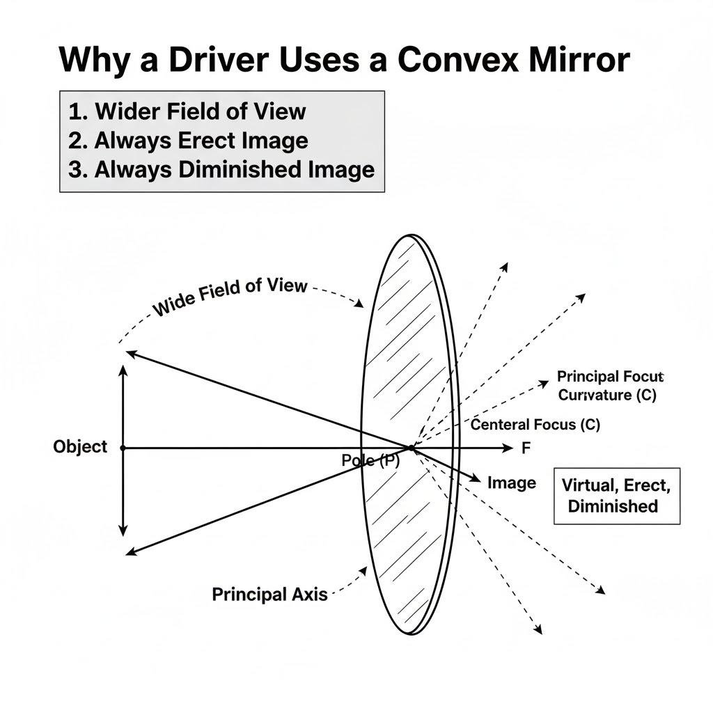
Exercise 7 (C)
Question 1.
For an incident ray directed towards centre of curvature of a spherical mirror the reflected ray:
- Retraces its path
- Passes through the focus
- Passes through the pole
- Becomes parallel to the principal axis.
Question 2.
The image formed by a convex mirror is
- Erect and diminished.
- Erect and enlarged.
- Inverted and diminished.
- Inverted and enlarged.
Question 3.
A real and enlarged image can be obtained by using a
- Convex mirror
- Plane mirror
- Concave mirror
- Either convex or plane mirror.
Exercise 7 (C)
Question 1.
The radius of curvature of a convex mirror is 40 cm. Find its focal length.
Ans:
Finding the Focal Length of a Convex Mirror
This problem involves a fundamental concept in optics: the relationship between the radius of curvature and the focal length of a spherical mirror. Let’s solve it step-by-step.
Step 1: Understanding the Key Relationship
For any spherical mirror—whether it’s concave or convex—the focal length (denoted by f) is exactly half of its radius of curvature (denoted by R). This is a standard principle in physics.
The formula is:
Focal Length (f) = Radius of Curvature (R) / 2
Step 2: Interpreting the Sign Convention
To get the correct answer, we must use the Cartesian sign convention. This convention is crucial because it helps us distinguish between convex and concave mirrors mathematically.
- The Radius of Curvature (R) is the distance from the mirror’s pole to its center of curvature.
- For a convex mirror, the center of curvature lies behind the mirror. According to the sign convention, distances measured behind the mirror are taken as positive.
- Therefore, for a convex mirror, the radius of curvature is positive.
Step 3: Applying the Values to the Formula
We are given:
- Radius of Curvature, R = 40 cm
Using the formula from Step 1:
f = R / 2
Substituting the value:
f = 40 cm / 2
Step 4: Performing the Calculation and Stating the Sign
The numerical calculation is simple:
f = 20 cm
Question 2.
The focal length of a concave mirror is 10 cm. Find its radius of curvature.
Ans:
The connection between a mirror’s focal length and its radius of curvature is direct and consistent. The focal length is exactly half the distance of the radius of curvature.
For any spherical mirror, the focal point lies exactly midway between the pole and the center of curvature. This fundamental relationship is described by the formula:
(R) = 2 × Focal Length (f)
We are told the mirror is concave and has a focal length (f) of 10 cm. Since it is a concave mirror, we treat the focal length as negative based on the sign convention, which gives its position relative to the pole.
Therefore, the calculation for its radius of curvature (R) is:
R = 2 × f
R = 2 × (-10 cm)
R = -20 cm
The negative sign in the result simply confirms that the center of curvature is located on the same side of the mirror as the incident light, which is a standard characteristic of a concave mirror.
Final Result: The radius of curvature is 20 cm.
Question 3.
An object of height 2 cm is placed at a distance of 20 cm in front of a concave mirror of a focal length of 12 cm. Find the position, size, and nature of the image.
Ans:
Analyzing the Image in a Concave Mirror
Let’s determine the image formed by a concave mirror using the standard mirror conventions, where any distance measured toward the incoming light is considered negative.
What We Know:
- The object stands 2 cm tall. Since it’s placed upright, we assign its height a positive value: +2 cm.
- Following the convention, this distance is negative: -20 cm.
- The mirror’s focal point is 12 cm in front of it. For a concave mirror, this is also negative: -12 cm.
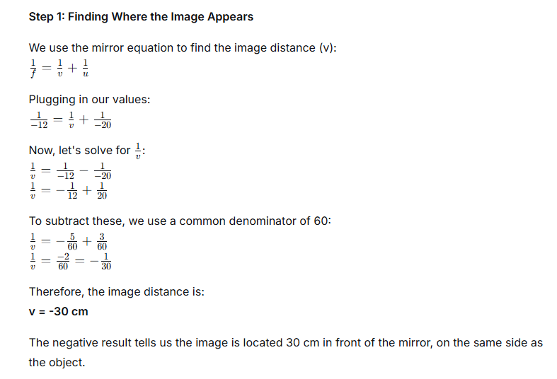
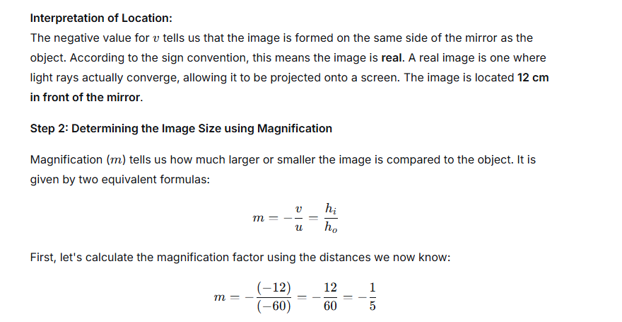
Question 4.
An object is placed at 4 cm distance in front of a concave mirror of radius of curvature 24 cm. Find the position of the image. Is the image magnified?
Ans:
Analyzing an Image Formed by a Concave Mirror
Let’s work through a classic optics problem involving a concave mirror. We are given that an object is placed 4 cm in front of the mirror, and the mirror itself has a radius of curvature of 24 cm. Our goal is to find out where the image forms and determine its characteristics, specifically if it is magnified.
To solve this, we will use the Cartesian sign convention, which is the standard in optics. In this system:
- Distances measured in front of the mirror (where the object is and real images form) are taken as negative.
- Distances measured behind the mirror (where virtual images form) are taken as positive.
- The focal length (*f*) of a concave mirror is negative because its focus lies in front of it.
Step 1: Determine the Focal Length
The focal length of a spherical mirror is simply half of its radius of curvature.
- Radius of Curvature, R = 24 cm
- Focal Length, *f* = R / 2 = 24 cm / 2 = 12 cm
Since this is a concave mirror, we apply the sign convention:
*f = -12 cm*
Step 2: Identify the Object Distance
The object is placed 4 cm in front of the mirror. According to our convention:
*u = -4 cm*
Step 3: Apply the Mirror Formula
The mirror formula is a fundamental relationship that connects the object distance (*u*), the image distance (*v*), and the focal length (*f*):
1/*f* = 1/*v* + 1/*u*
Let’s plug in our known values:
1 / (-12) = 1/*v* + 1 / (-4)
This gives us:
-1/12 = 1/*v* – 1/4
Step 4: Solve for the Image Distance (*v*)
Now, we solve the equation for 1/*v*:
1/*v* = -1/12 + 1/4
To add these fractions, we need a common denominator, which is 12:
1/*v* = -1/12 + 3/12
1/*v* = (-1 + 3) / 12
1/*v* = 2 / 12
1/*v* = 1 / 6
Taking the reciprocal of both sides gives us the image distance:
*v = +6 cm*
Step 5: Interpret the Image Position
The positive sign for *v* is highly significant. It tells us that the image is formed behind the mirror. An image located behind a mirror cannot be projected onto a screen; it is a virtual image. Virtual images are always upright (erect) relative to the object.
Step 6: Calculate the Magnification
Magnification (*m*) tells us how much larger or smaller the image is compared to the object. It is given by the formula:
*m* = – (*v* / *u*)
Substituting our values:
*m* = – ( (+6) / (-4) )
*m* = – ( -1.5 )
*m = +1.5*
Step 7: Analyze the Image Characteristics
Let’s break down what the magnification value of +1.5 tells us:
- Size: The magnitude of the magnification is 1.5. Since this is greater than 1, the image is magnified (or enlarged) to 1.5 times the size of the object.
- Orientation: The sign of the magnification is positive. This means the image is erect (upright).
Final Summary
For a concave mirror with a focal length of 12 cm, placing an object 4 cm in front of it (which is between the mirror’s pole and its focal point) results in the following image:
- Location: 6 cm behind the mirror.
- Nature: Virtual and erect.
- Size: Magnified, 1.5 times the object’s size.
Question 5.
At what distance from a concave mirror of focal length 25 cm should an object be placed so that the size of image is equal to the size of the object.
Ans:
To obtain a life-sized image from a concave mirror, the object must be placed at a specific point. This scenario produces a real and inverted image that matches the object’s dimensions exactly. The only position that fulfills this requirement is when the object is located at the mirror’s center of curvature.
Let’s determine this position using the given focal length.
We know the focal length (f) is 25 cm. In mirror terminology, the center of curvature lies at a distance from the mirror that is exactly twice the focal length. This distance is known as the radius of curvature (R).
Therefore, we calculate:
Radius of Curvature, R = 2 × f
R = 2 × 25 cm
R = 50 cm
Placing the object at this 50 cm mark is the key. At this location, light rays reflecting off the mirror converge to form an image that is also precisely 50 cm in front of the mirror. The result is a real image that is a perfect, albeit inverted, copy of the object in terms of its size.
Final Answer:
The object should be placed 50 cm from the pole of the concave mirror.
Question 6.
An object 5 cm high is placed at a distance 60 cm in front of a concave mirror of focal length 10 cm. Find the position and size of the image.
Ans:
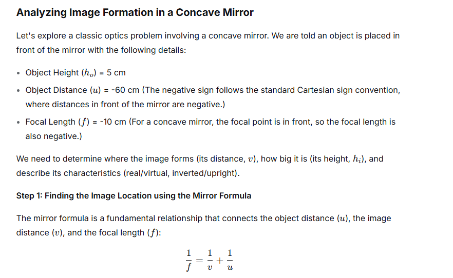
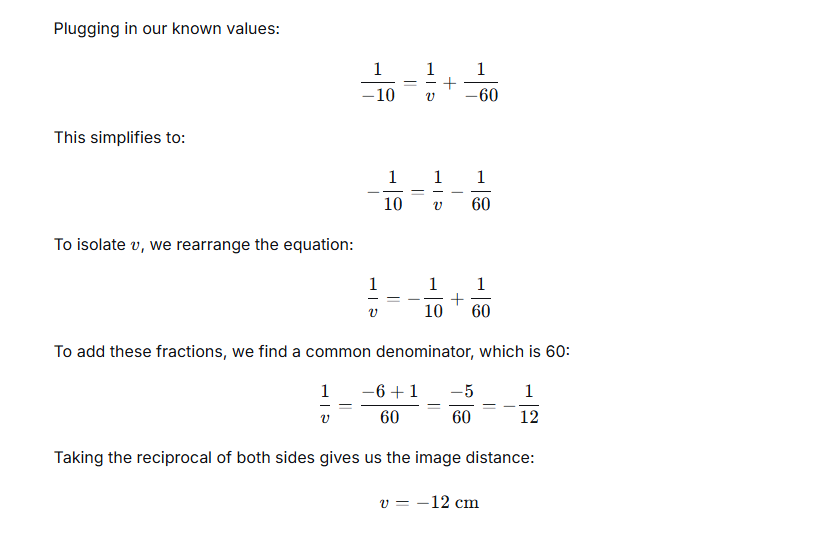
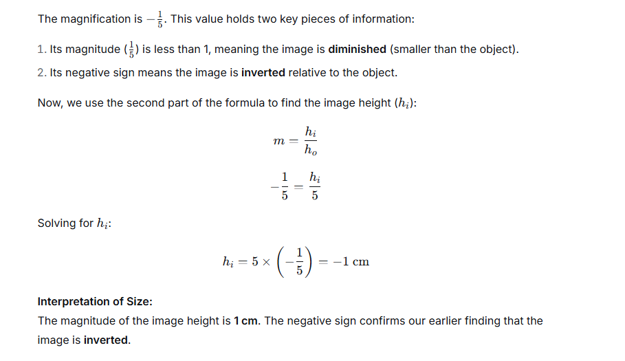
Question 7.
A point light source is kept in front of a convex mirror at a distance of 40 cm. The focal length of the mirror is 40 cm. Find the position of the image.
Ans:

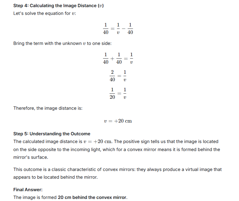
Question 8.
When an object of height 1 cm is kept at a distance 4 cm from a concave mirror, its erect image of height 1.5 cm is formed at a distance 6 cm behind the mirror. Find the focal length of the mirror, by drawing.
Ans:
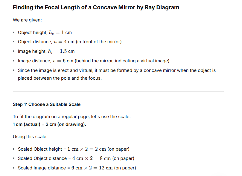
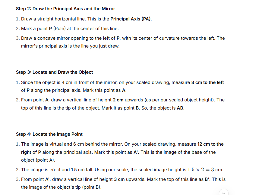
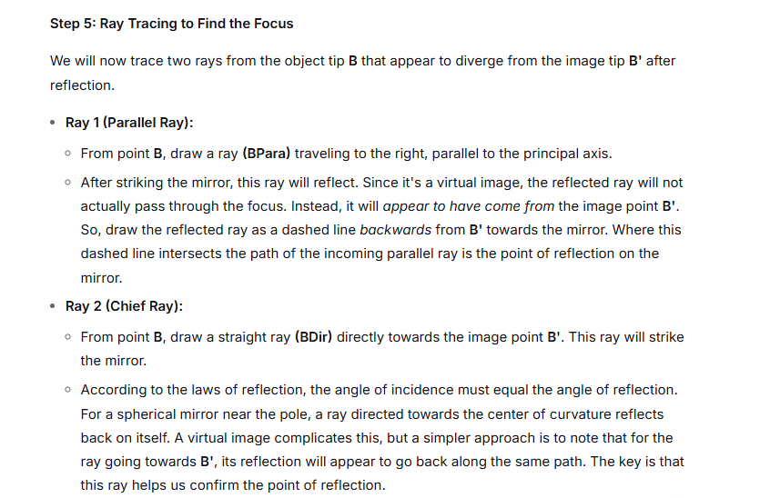

Question 9.
An object of length 4 cm is placed in front of a concave mirror at a distance of 30 cm. The focal length of the mirror is 15 cm. Where will the image form? What will be the length of the image?
Ans:
We use the mirror formula: 1/v + 1/u = 1/f
Here:
- Object distance, u = -30 cm (negative by convention)
- Focal length, f = -15 cm (negative for a concave mirror)
Plugging in the values:
1/v + 1/(-30) = 1/(-15)
1/v – 1/30 = -1/15
1/v = -1/15 + 1/30
1/v = (-2 + 1)/30
1/v = -1/30
Therefore, the image distance is v = -30 cm.
The image forms 30 cm in front of the mirror.
Now, for the size of the image, we use the magnification formula:
m = -v/u = hᵢ/hₒ
We know:
- v = -30 cm
- u = -30 cm
- Object height, hₒ = 4 cm
First, find the magnification (m):
m = -(-30) / (-30)
m = 30 / (-30)
m = -1
The magnification is -1.
Now, find the image height (hᵢ):
m = hᵢ / hₒ
-1 = hᵢ / 4
hᵢ = -4 cm
The length of the image is 4 cm.
Final Answer:
- Image Location: 30 cm in front of the mirror.
- Image Length: 4 cm (inverted and real).
Question 10.
A concave mirror forms a real image of an object placed in front of it at a distance 30 cm, of size three times the size of object. Find the focal length of the mirror position of the image.
Ans:
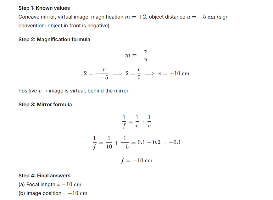
Question 11.
A concave mirror forms a virtual image of size twice that of the object placed at a distance 5 cm from it.
Find : (a) the focal length of the mirror (b) position of image
Ans:

Question 12.
The image formed by a convex mirror is one third the size of the object. How are u and v related?
Ans:
Question 13.
The erect image formed by a concave mirror is double the size of the object. How are u and v related?
Ans:
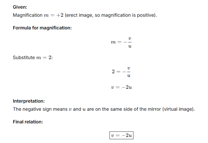
Question 14.
The magnification for a mirror is -3. How are u and v related?
Ans:
