
")
The foundational concept of current electricity begins with understanding electric charge in motion. When charges, typically electrons, flow systematically through a conductor, they constitute an electric current. This flow is driven by an external source, called an electric cell or battery, which creates a potential difference—often termed voltage—between two points in a circuit. Think of this potential difference as an electrical pressure that pushes the charges, with the conventional direction of current being from the positive terminal to the negative terminal of the battery, even though electrons actually move in the opposite direction. The amount of current flowing is quantitatively defined as the rate of flow of charge, and its SI unit is the Ampere. For a current to be sustained, there must be a closed, continuous path known as an electric circuit.
The flow of current through a material is not unopposed; this inherent property of a conductor to resist the flow of charges is known as resistance. Resistance depends on the material’s nature, its length, cross-sectional area, and temperature. This relationship is defined by Ohm’s Law, a cornerstone of this chapter, which states that the potential difference across a conductor is directly proportional to the current flowing through it, provided the physical conditions like temperature remain constant. The constant of proportionality is the resistance, measured in Ohms. This leads to the formula V = IR, which is used extensively to analyze simple circuits. Factors affecting resistance are crucial; for instance, resistance increases with the length of the conductor but decreases when its area of cross-section is increased.
To practically apply these principles, we study the combination of resistors, which can be arranged in series or in parallel. In a series connection, the current has only one path, the total resistance is the sum of individual resistances, and the same current flows through each component. In contrast, a parallel connection provides multiple paths for the current; here, the voltage across each resistor is the same, but the total current is the sum of the currents in the different branches, leading to an overall resistance that is less than the smallest individual resistance. Finally, the chapter explores the heating effect of electric current, where electrical energy is converted into heat energy, as described by Joule’s Law. This principle is the working basis for many household appliances like electric heaters and incandescent bulbs.
Exercise 9 (A)
Question 1.
Name one D.C. source and one A.C. source.
Ans:
D.C. Source: A common alkaline battery, like a standard AA cell you would use in a television remote. It provides a steady, one-way flow of electrical current from its positive to its negative terminal until its chemical energy is depleted.
A.C. Source: The power outlet in a standard household wall in most countries. This source provides an electric current that rapidly and continuously reverses its direction, cycling back and forth many times per second to efficiently deliver power over long distances.
Question 2.
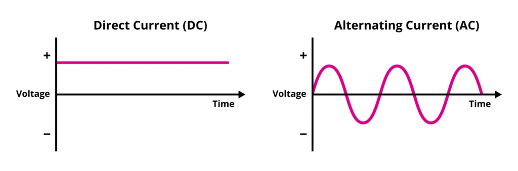
Distinguish between D.C. and A.C.
Ans:
| Feature | Direct Current (D.C.) | Alternating Current (A.C.) |
| Flow of Electrons | Electrons flow only in one single direction (unidirectional). | Electrons periodically reverse their direction (bidirectional). |
| Voltage/Current Graph | Remains constant (or steady) over time. | Changes polarity and magnitude over time, typically following a sine wave. |
| Generation | Generated by sources like batteries, solar cells, and D.C. generators. | Generated by A.C. generators and alternators. |
| Transmission | Difficult and inefficient to transmit over long distances without significant energy loss. | Easy and efficient to transmit over long distances at high voltage using transformers. |
| Polarity | Has a fixed polarity (positive and negative terminals). | Polarity reverses many times per second (e.g., 50 or 60 times per second, which is the frequency). |
| Conversion | Can be converted from A.C. using a rectifier. | Can be converted from D.C. using an inverter. |
| Common Uses | Used in electronic devices, batteries, electric vehicles, and low-voltage applications. | Used in homes, offices, and industries for powering appliances, lighting, and heavy machinery. |
Question 3.
What is an electric cell?
Ans:
An electric cell is a device that converts chemical energy into electrical energy to provide a constant source of direct current (DC).
Key Components and Function
- Electrodes: A cell contains two terminals, typically metallic plates or rods, called electrodes.
- The Positive Electrode (Anode)
- The Negative Electrode (Cathode)
- Electrolyte: The electrodes are immersed in a chemical solution or paste called the electrolyte.
- Function: Through chemical reactions occurring within the electrolyte, electric charges are separated. This process builds up an electrical potential difference (voltage) between the two electrodes. When the electrodes are connected to an external circuit, this potential difference causes electrons to flow from the negative electrode to the positive electrode, providing a continuous electric current.
Cell vs. Battery
It’s important to note the distinction between a cell and a battery:
- A Cell is a single unit that produces voltage (like a standard AA or AAA unit).
- A Battery is a combination of two or more cells connected together to produce a higher voltage or more power.
Question 4.
What transformation of energy takes place when current is drawn from a cell?
Ans:
The main energy transformation that takes place when current is drawn from a cell is the conversion of Chemical Energy into Electrical Energy.
The chemical reactions within the cell consume stored chemical compounds, releasing energy that drives the flow of electrons through the external circuit.
Question 5.
Name the constituents of a cell.
Ans:
The primary constituents of a cell are the cell membrane, the cytoplasm, and the nucleus (in eukaryotic cells).
Basic Constituents of a Cell
- Cell Membrane (Plasma Membrane): The outer boundary that encloses the cell.
- Cytoplasm: The jelly-like substance filling the cell, outside the nucleus. It contains water, nutrients, salts, and the cell’s organelles.
- Nucleus: The control center of the cell (in eukaryotes). It contains the genetic material (chromosomes/DNA). (Note: Prokaryotic cells lack a true nucleus, but their genetic material is located in a region called the nucleoid.)
- Organelles: The specialized subunits within the cytoplasm that perform specific functions (e.g., mitochondria, endoplasmic reticulum, ribosomes).
Question 6.
State the two kinds of cell. Give one example of each.
Ans:
| Cell Kind | Key Characteristic | Example |
| Prokaryotic Cell | Lacks a true nucleus and other membrane-bound organelles. They are typically smaller and simpler. | Bacteria (e.g., E. coli) |
| Eukaryotic Cell | Possesses a true nucleus enclosed by a membrane, as well as other membrane-bound organelles (e.g., mitochondria). They are typically larger and more complex. | Animal cells (e.g., a human nerve cell) or Plant cells |
Question 7.
1. What is a primary cell?
2. Name two primary cells.
Ans:
What is a primary cell?
A primary cell is an electric cell that is designed to be used only once and cannot be electrically recharged. The chemical reaction that produces the electric energy is essentially irreversible. Once the active chemical materials are consumed, the cell must be discarded.
Name two primary cells.
Two common examples of primary cells are:
- Dry Cell (Leclanché cell or Zinc-Carbon cell)
- Alkaline Cell
Question 8.
1. What is a secondary cell?
2. Name one secondary cell.
Ans:
1. A secondary cell (or storage battery) is an electrochemical cell that can be recharged after its chemical energy is depleted by passing an electric current through it in the reverse direction. The chemical reactions within a secondary cell are reversible.
2. One common secondary cell is a Lead-acid battery (used in cars).
Question 9.
State three differences between the primary and secondary cells.
Ans:
| Feature | Primary Cells (Non-Rechargeable) | Secondary Cells (Rechargeable) |
| Rechargeability | Cannot be recharged. They are designed for single use and must be discarded when depleted. | Can be recharged and reused multiple times by passing a current through them in the reverse direction. |
| Chemical Reaction | Involve irreversible chemical reactions. The original reactants cannot be regenerated. | Involve reversible chemical reactions. The charging process regenerates the original reactants. |
| Typical Use | Best for devices requiring low, intermittent current or long storage life (e.g., remote controls, wall clocks, flashlights). | Best for devices requiring high, continuous current or frequent use (e.g., smartphones, laptops, electric vehicles). |
Question 10.
What do you understand by the term current? State and define its S.I. unit.
Ans:
Understanding Electric Current
At its heart, electric current is the organized movement of electric charge. A helpful way to picture it is to imagine a stream of water flowing through a channel. In this analogy, the individual water droplets represent the electric charges—which are often electrons in a metal wire. The consistent movement of these droplets along the channel represents the electric current.
In more precise language, electric current is defined as the rate at which electric charge flows past a specific point in a conductor. It quantifies how much charge is moving and how quickly.
The Standard Unit: The Ampere
The fundamental unit for measuring this flow of charge in the International System of Units (SI) is the Ampere, with the symbol A.
Unlike units for speed (meters per second) which are built from other units, the Ampere is a base unit. Its definition is not derived but is established through a fundamental property of nature.
How the Ampere is Defined:
The official definition of one ampere is rooted in the magnetic interaction between currents. It is the constant current which, when flowing through two infinitely long, parallel wires placed one meter apart in a vacuum, results in a specific magnetic force between them. This force is precisely 0.0000002 newtons (or 2 × 10⁻⁷ N) for each meter of the wires’ length.
Essentially, this definition anchors the unit to a repeatable, physical experiment based on magnetic force, providing a universal standard for measurement.
What This Means in Everyday Use:
When a household appliance, like a lamp, operates at a current of one ampere, it signifies an immense number of electrons streaming through its wiring each second. To put a number to it, one ampere corresponds to roughly six quintillion, two hundred forty quadrillion electrons passing a given point every second. This staggering figure helps illustrate that even a modest electrical current involves the movement of a vast number of microscopic charges.
Question 11.
How much is the charge on an electron?
Ans:
The charge on an electron is -1.602 x 10^-19 coulombs.
Question 12.
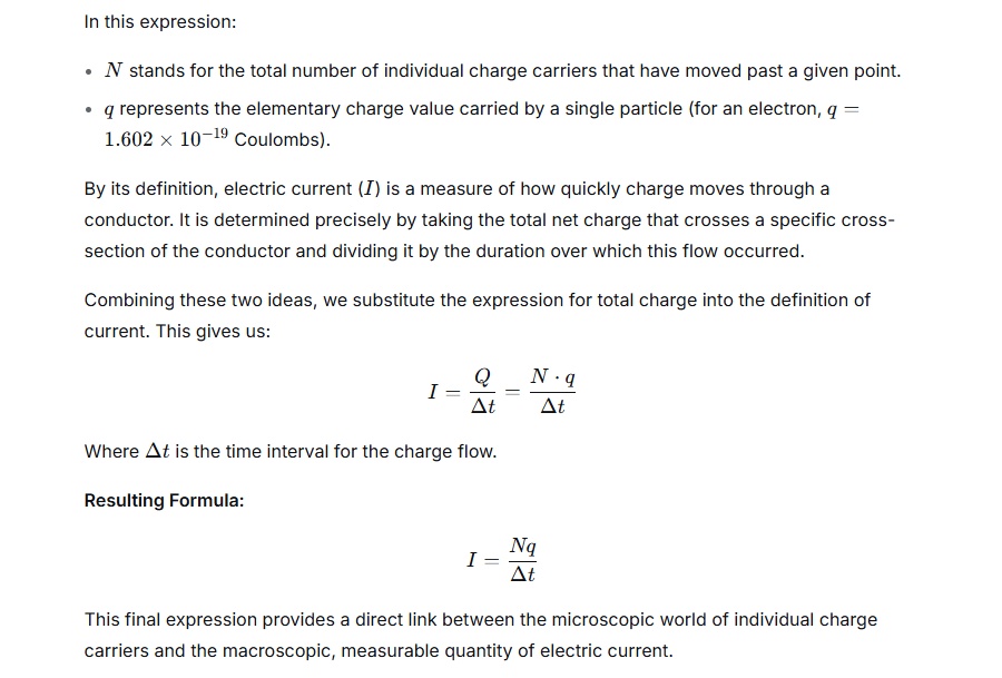
n electrons flow through a cross section of a conductor in time t. If charge on an electron is e, then write an expression for the current in the conductor.
Ans:
The movement of electric charge constitutes what we know as an electric current. A fundamental way to quantify this is by considering the flow of individual charge carriers, such as electrons.
To find the aggregate amount of charge that has been transported, you calculate the product of the total count of these moving particles and the fundamental charge each one carries.
This leads to the relationship for the total charge, denoted by
Q:Q=N⋅q
Question 13.
Name the instrument used to control the current in an electric circuit.
Ans:
Managing the Flow of Electricity: The Role of Adjustable Resistors
In any electric circuit, regulating the movement of current is a fundamental requirement. The component traditionally tasked with this role is the rheostat. This device functions as an adjustable resistor, capable of varying the electrical resistance in a circuit without interrupting the connection. By turning a knob or sliding a control, you physically change the length of a resistive wire through which the current must travel. A longer path means higher resistance, which in turn reduces the current flow, and a shorter path allows more current to pass.
While the term “rheostat” is precise, you will often find this current-controlling job performed by more common components like variable resistors and potentiometers. The distinction often lies in their construction and connection.
A standard two-terminal variable resistor, sometimes labeled with an “R” for resistance, is used in the exact same way as a classic rheostat. It is wired into the circuit to provide a controllable level of resistance, thereby dictating the current.
A potentiometer, typically a three-terminal device, is more versatile. In one common setup, it can be wired to function identically to a rheostat, using just two of its three terminals. This makes it a popular and cost-effective choice for many modern applications where simple current adjustment is needed, such as dimming a light or controlling the speed of a motor.
Question 14.
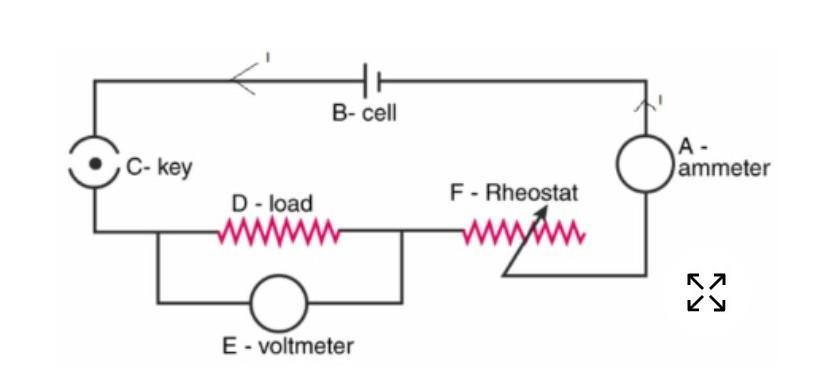
In the electric circuit shown in Figure, label the parts A, B, C, D, E, and F. State the function of each part. Show in the diagram the direction of flow of current.
Ans:
Labeled Parts and Their Functions
A typical simple electric circuit consists of the following components:
- A: Cell / Battery
Function: It is the source of electrical energy for the circuit. It provides the electromotive force (EMF) or voltage that pushes the electric charges, creating a potential difference and enabling the flow of current.
- B: Switch (Open)
Function: It acts as a gate or a controller for the circuit. When open (as shown), it creates a break in the path, stopping the flow of current. When closed, it completes the path, allowing current to flow.
- C: Connecting Wires
Function: These are usually metallic conductors (like copper) that provide a continuous, low-resistance path for the electric current to flow, connecting all the other components together to form a complete loop.
- D: Resistor
Function: This component limits or regulates the flow of electric current in the circuit. It also converts electrical energy into heat energy. In a real-world application, this could be a component like a light bulb or an LED, which resists current and glows.
- E: Ammeter
Function: It is a measuring instrument connected in series with the circuit to measure the magnitude of the electric current flowing through it, typically in Amperes (A).
- F: Voltmeter
Function: It is a measuring instrument connected in parallel across a component (like the resistor) to measure the potential difference (voltage) between its two terminals, typically in Volts (V).
Diagram Showing Direction of Current Flow
Below is a schematic diagram of the circuit with all parts labeled and the direction of current flow indicated.
text +——————————+
| |
[A] [F] (Voltmeter)
(Battery) |
| |
+—[B]—[C]—-[E]—[D]—–+
| (Wires) | (Resistor)
(Switch) (Ammeter)
(in Series)
**Direction of Conventional Current:**
+–> (from positive terminal to negative terminal of the battery)
Explanation of Current Flow:
The direction of the flow of current is indicated by the arrows ( —> ).
- Electric current flows from the positive terminal of the battery (A), through the closed switch (B), through the ammeter (E), through the resistor (D), and back to the negative terminal of the battery.
- The voltmeter (F) is connected in parallel across the resistor (D) to measure the voltage drop without interrupting the main current flow.
- This direction, from the positive terminal to the negative terminal, is known as Conventional Current Flow. (Note: The physical flow of electrons is in the opposite direction, from negative to positive, but conventional current is the standard used for circuit diagrams and analysis).
Question 15.
What is the function of a key (or switch) in an electric circuit?
Ans:
The function of a key (or switch) in an electric circuit is to act as a control device to either complete (close) or break (open) the circuit.
- Closed Switch (ON): Completes the circuit, allowing current to flow and the device (like a bulb) to operate.
- Open Switch (OFF): Breaks the circuit, stopping the flow of current, and turning the device off.
Essentially, it acts as a gatekeeper to control the flow of electrical energy.
Question 16.
1. Write symbol and state function of the following component in an electric circuit : key
2. Write symbol and state function of following component in an electric circuit :
cell
3. Write symbol and state function of following component in an electric circuit :
rheostat
4. Write symbol and state function of following component in an electric circuit :
ammeter
5. Write symbol and state function of following component in an electric circuit :
Voltmeter
Ans:
1. Key (or Switch)
- Symbol:
(Open/Off) | (Closed/On) - Function: A key functions as a gatekeeper for the flow of electric current in a circuit. When open (off), it creates a break in the circuit path, stopping the current completely. When closed (on), it completes the circuit path, allowing current to flow unimpeded. It is the primary component for controlling a circuit’s operation.
2. Cell
- Symbol:
- Function: A cell acts as a single-unit source of electrical energy by converting stored chemical energy into electrical energy. It provides the electromotive force (EMF) or voltage that pushes electric charge through a circuit, establishing the potential difference needed for current to flow.
3. Rheostat
- Symbol:
or - Function: A rheostat serves as an adjustable resistor, specifically used to control the amount of current flowing in a circuit. By sliding its contact, the effective length of the resistive wire inside the circuit is changed, thereby varying the resistance and allowing for precise manual control over current levels, such as in a light dimmer or motor speed controller.
4. Ammeter
- Symbol:
(The letter ‘A’ inside the circle) - Function: An ammeter is a measuring instrument designed to quantify the rate of flow of electric charge, which is the electric current, through a circuit. It is always connected in series with the component whose current is being measured so that the same current passes through it. Its internal resistance is extremely low to avoid altering the current it is trying to measure.
5. Voltmeter
- Symbol:
(The letter ‘V’ inside the circle) - Function: A voltmeter is a measuring instrument used to find the difference in electrical potential between two points in a circuit, known as voltage. It is always connected in parallel across the component or section of the circuit where the potential difference is to be measured. Its internal resistance is very high to ensure it draws negligible current and does not disturb the circuit’s operation.
Question 17.
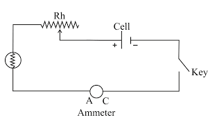
(a) Complete the circuit given in Fig. by inserting between the terminals A and C. an ammeter.
(b) In the diagram, mark the polarity at the terminals of the ammeter and indicate clearly the direction of flow of current in the circuit when the circuit is complete.
(c) Name and state the purpose of Rh in the circuit.
Ans:
(a) Completing the circuit with an ammeter
An ammeter is used to measure the current flowing through a circuit and must be connected in series with the components. To insert it between terminals A and C, it should be placed in the path of the main current, before the parallel branches containing the resistors and the voltmeter. The circuit diagram would be modified so that the wire connecting point A directly to point C is removed and replaced with the ammeter symbol.
(b) Polarity and direction of current flow
- Polarity of the Ammeter: The positive terminal of the ammeter (marked ‘+’) should be connected to point A, which is connected to the positive terminal of the battery. The negative terminal of the ammeter (marked ‘–’) should be connected to point C.
- Direction of Current Flow: Conventional current flows from the positive terminal of the battery to the negative terminal. Therefore, the direction of current flow will be:
- Out from the battery’s positive terminal.
- Into the ammeter at its positive (+) terminal.
- Out of the ammeter from its negative (–) terminal towards point C.
- Then through the rest of the circuit and back to the negative terminal of the battery.
(c) Purpose of R<sub>h</sub>
- Name: R<sub>h</sub> is called a Rheostat.
- Purpose: The purpose of the rheostat R<sub>h</sub> in this circuit is to vary the amount of current flowing in the main circuit. By changing the resistance of the rheostat, we can control the total current and hence the potential difference across the resistor (which is measured by the voltmeter). This allows for taking multiple sets of readings of current and voltage, which can be used to verify Ohm’s Law or to study the relationship between them for a given resistor.
Question
18. What are conductors and insulators of electricity? Give two examples of each.
Ans:
Conductors of Electricity
Conductors are materials that allow electric charge (current) to flow easily through them. They have a large number of free electrons that can move readily when a voltage is applied.
- Function: To transmit electric current.
- Examples:
- Copper: Widely used in electrical wiring and cables.
- Aluminum: Used in overhead power transmission lines.
Insulators of Electricity
Insulators are materials that strongly resist the flow of electric charge. They have very few free electrons, and their electrons are tightly bound to the atoms, preventing the easy passage of current.
- Function: To prevent the flow of electric current and provide protection.
- Examples:
- Rubber: Used as a protective covering (sheathing) for electrical wires.
- Glass: Used in electrical components and as electrical supports (insulators) on power lines.
Question 19.
Select conductors of electricity from the following: Copper wire, silk thread, pure water, acidulated water, human body, glass, mercury.
Ans:
The conductors of electricity from the list you provided are:
- Copper wire: Copper is a metal and an excellent conductor due to the presence of a large number of free electrons.
- Acidulated water: The acid dissolves in the water, producing mobile ions (H+ and anions) that can carry electric charge, making it a good conductor (electrolyte).
- Human body: The human body contains a high percentage of water and dissolved salts (electrolytes), which provide the necessary ions to conduct electricity.
- Mercury: Mercury is a liquid metal. Like all metals, it has free electrons that make it a good electrical conductor.
| Material | Classification | Reason |
| Copper wire | Conductor | Metal with abundant free electrons. |
| Silk thread | Insulator | Lacks free electrons to carry current. |
| Pure water | Insulator (Very poor conductor) | Has very few ions to carry charge. |
| Acidulated water | Conductor | Contains mobile ions from the added acid. |
| Human body | Conductor | Contains water and electrolytes (ions). |
| Glass | Insulator | Lacks free electrons. |
| Mercury | Conductor | A liquid metal with free electrons. |
Question 20.
State two differences between a conductor and an insulator of electricity.
Ans:
| Feature | Conductor | Insulator |
| Free Electrons | Possesses a large number of free electrons that are loosely bound to atoms and can move easily throughout the material. | Has very few (almost negligible) free electrons; electrons are tightly bound to their atoms and cannot move easily. |
| Electrical Resistance | Has very low resistance, allowing electric current to flow through easily. | Has extremely high resistance, strongly opposing the flow of electric current. |
| Role in Circuits | Used to carry/transmit current (e.g., wires, filaments). | Used to block/isolate current (e.g., protective coatings, circuit boards). |
| Examples | Metals like Copper, Gold, Aluminum. | Non-metals like Rubber, Plastic, Glass. |
Question 21.
Distinguish between a closed circuit and an open circuit, with the use of suitable labelled diagrams.
Ans:
A closed circuit allows electric current to flow continuously, while an open circuit has a break that stops the flow of current.
Here is a distinction with labeled diagrams:
Closed Circuit (Complete Circuit)
A closed circuit is a complete path for the electric current to flow from the source’s positive terminal to its negative terminal.
- Current Flow: Current flows through the circuit.
- Device Operation: Electrical devices (like a bulb) in the circuit operate (e.g., the bulb lights up).
- Switch State: The switch is closed (ON).
Diagram of a Closed Circuit
Open Circuit (Incomplete Circuit)
An open circuit is a broken or incomplete path in the electrical flow. The break can be due to a disconnected wire or an open switch.
- Current Flow: Current does not flow through the circuit.
- Device Operation: Electrical devices in the circuit do not operate (e.g., the bulb does not light up).
- Switch State: The switch is open (OFF).
Diagram of an Open Circuit
Key Differences
| Feature | Closed Circuit | Open Circuit |
| Path | Complete and continuous. | Broken or incomplete. |
| Current | Current flows. | Current does not flow (or stops). |
| Switch | Closed (ON position). | Open (OFF position). |
| Effect | Electrical device works. | Electrical device does not work. |
Question 22.
Write the condition required for a circuit to be a closed circuit.
Ans:
The fundamental requirement for an electrical circuit to be closed is that it must establish an uninterrupted, conductive pathway that links the high-potential (positive) terminal of the power source to its low-potential (negative) terminal.
Here are the crucial elements of this condition:
- Complete Loop (Continuity): The path must form a continuous circuit without any gaps, breaks, or open switches. Electricity cannot “jump” across a void, so the connection must be total.
- Current-Carrying Materials (Conductivity): Every part of the path—including the wires, components, and any control device (like a switch)—must be made of materials that allow electric current to flow effectively (i.e., they must be electrical conductors).
- Source Engagement (Terminal Connection): The circuit must successfully bridge the two sides of the power source. Both the high-potential and low-potential terminals of the battery or generator need to be part of the continuous loop.
Simply put, a closed circuit is one where the electric current is free to circulate completely from its origin, through the connected devices (loads), and back to the source. If this loop is broken at any point, the circuit becomes an open circuit, and current flow immediately ceases.
Exercise 9 (A)
Question 1.
A cell is used to :
- measure current in a circuit
- provide current in a circuit
- check current in a circuit
- prevent current in a circuit.
Question 2.
The unit of current is :
- ampere
- volt
- ohm
- coulomb
Question 3.
The insulator of electricity is :
- Copper
- Acidulated water
- Human body
- Silk
Exercise 9 (A)
Question 1.
A charge 0.5 C passes through a cross section of a conductor in 5 s . Find the current .
Ans:
We are given a simple scenario from electrical science: an amount of electric charge, quantified as 0.5 Coulombs, is transferred along a conductor over a duration of 5 seconds. Our task is to determine the electric current flowing in the conductor.
The core principle we apply is the definition of a steady electric current. Current is not just the presence of charge but is specifically defined as the rate at which that charge moves past a given point. In simpler terms, it’s a measure of charge flow per unit of time.
This definition is captured by a fundamental formula:
Electric Current (I) = Total Charge (Q) / Time Interval (t)
The standard scientific units for these quantities are:
- Charge (Q) is measured in Coulombs (C)
- Time (t) is measured in seconds (s)
- Current (I) is measured in Amperes (A), where 1 Ampere is equivalent to a flow of 1 Coulomb of charge every second (1 A = 1 C/s).
With the provided values, we can proceed with a direct calculation:
- Identify the known values:
- Q = 0.5 C
- t = 5 s
- Apply the values to the formula:
I = Q / t
I = 0.5 C / 5 s - Perform the division:
I = 0.1 C/s - Express the result in its proper unit:
Since Coulombs per second (C/s) is the definition of an Ampere, we state the final answer as:
I = 0.1 A
Question 2.
A current of 1.5 A flows through a conductor for 2.0 s . What amount of charge passes through the conductor ?
Ans:
A useful parallel is to think of a crowd moving through a corridor. The total number of people in the crowd is like electrical charge, for which the unit is the coulomb (C). How fast these people are passing a specific point in the corridor—the number of people per second—mirrors the idea of electric current. We measure this flow in amperes (A).
These two ideas, the total quantity and its rate of flow, are bound together by a straightforward relationship:
Total Charge = (Rate of Flow) × (Duration of Flow)
In the language of physics, this is captured by the formula:
Q = I × t
Here is what each symbol stands for:
- Q is the total electric charge moved, measured in coulombs (C).
- I is the current, or the rate of charge flow, measured in amperes (A).
- t is the duration for which the current flows, measured in seconds (s).
In essence, this equation allows you to calculate the total “amount of electricity” that has been delivered by knowing how fast it was moving and for how long.
Putting the Formula to Work
Consider this scenario:
- A steady current, I, of 1.5 amperes flows through a wire.
- This flow continues for a time, t, of 2.0 seconds.
To find the total charge, Q, that has traveled through the wire, we apply the formula:
Q = I × t
Q = (1.5 A) × (2.0 s)
Q = 3.0 A·s
Since an ampere-second (A·s) is defined as one coulomb, we conclude:
Q = 3.0 C
The result shows that a flow of 1.5 amperes sustained for two seconds results in a total charge transfer of three coulombs.
Question 3.
When the starter motor of a car is switched on for 0.8 s . A charge 24 C passes through the coil of the motor . Calculate the current in the coil .
Ans:
Step 1: Understanding the Problem
- A total electric charge of 24 Coulombs has been transferred.
- This transfer occurred over a time interval of 0.8 seconds.
Our objective is to determine the magnitude of the electric current.
Step 2: The Governing Principle
The fundamental definition of electric current is the rate at which electric charge flows past a specific point in a circuit.
Charge = Current × Time
or
Q = I × t
Where:
- Q is the charge in Coulombs (C)
- I is the current in Amperes (A)
- t is the time in seconds (s)
Step 3: Isolating the Unknown Variable
We need to find the current, I. By rearranging the standard formula, we solve for I by dividing both sides by time (t):
I = Q / t
Step 4: Inputting the Given Values
Inserting the known quantities into the derived equation:
I = 24 C / 0.8 s
Step 5: Performing the Calculation
Dividing 24 by 0.8 gives a result of 30.
I = 30 A
Final Result:
The electric current flowing in the coil is 30 Amperes.
Exercise 9 (B)
Question 1.
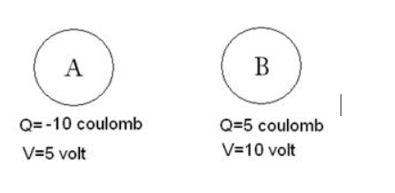
Figure. Below shows two conductors A and B. Their charges and potentials are given in diagram. State the direction of (i) flow of electrons and (ii) flow of current, when both the conductors are joined by a metal wire.
Ans:
Core Concept
When two conductors at different electric potentials are connected by a metal wire, charge flows from the conductor at a higher potential to the conductor at a lower potential. This flow continues until both conductors reach a common potential (equilibrium).
Assumed Scenario from the Problem
Based on typical problems of this nature, let’s assume the diagram indicates:
- Conductor A: Has a positive potential (e.g., +10 V).
- Conductor B: Has a lower or negative potential (e.g., 0 V or -5 V).
Therefore, Conductor A is at a higher electric potential than Conductor B.
Answers
(i) Direction of flow of electrons
Electrons are negatively charged particles.
- They are attracted towards a region of positive potential (or a deficiency of electrons).
- They are repelled from a region of negative potential (or an excess of electrons).
Since Conductor A is positive, it has a deficiency of electrons. Conductor B, being at a lower potential, has a relative excess of electrons.
Therefore, electrons will flow from Conductor B (lower potential) to Conductor A (higher potential) through the metal wire.
(ii) Direction of flow of current
By definition, conventional electric current is the direction in which positive charges would flow.
- Positive charge would naturally flow from a point of higher potential to a point of lower potential.
- This is the exact opposite of the actual flow of electrons.
Since electrons are flowing from B to A, the conventional current is defined as flowing from A to B.
Therefore, current flows from Conductor A (higher potential) to Conductor B (lower potential).
Question 2.
How is the direction of flow of current between the two charged conductors determined by their potentials?
Ans:
The direction of flow of conventional electric current between two charged conductors is determined by the difference in their electric potentials, specifically:
Current flows from the conductor at a higher (more positive) electric potential to the conductor at a lower (less positive or more negative) electric potential.
Key Principles
- Electric Potential: Electric potential is a measure of the electric potential energy per unit charge at a point. It dictates the “pressure” or drive for current flow, analogous to how pressure determines the flow of water or temperature determines the flow of heat.
- Current Flow Direction (Conventional): Conventional current is defined as the movement of positive charge. Therefore, it follows the direction of decreasing potential energy (from high potential to low potential).
- Flow Stops at Equilibrium: The flow of charge (current) continues only until both conductors reach the same electric potential. At this point, the potential difference is zero, and the electric field between them vanishes, halting the flow.
Analogy
Imagine two interconnected water tanks:
- Electric Potential is analogous to the water level.
- Electric Charge is analogous to the amount of water.
- Electric Current is analogous to the flow of water.
Water always flows from the tank with the higher water level (higher potential) to the tank with the lower water level (lower potential), regardless of the total amount of water in each tank, until the levels are equal. Similarly, current flows based on the potential difference, not the total charge on the conductors.
Question 3.
Explain the concept of electric potential difference in terms of work done in transferring the charge.
Ans:
Electric Potential Difference: The Electrical “Push”
Think of electric potential difference (voltage) as an electrical hill. A charge at the top of the hill has high potential energy, while at the bottom it has low potential energy.
The potential difference between two points is defined as the work you need to do to move a single, positive charge slowly from the low potential point to the high potential point, without accelerating it.
In simpler terms:
- It’s the work done per unit charge to move it between two points.
- If you have to do work to push a positive charge from point A to point B, then point B is at a higher electric potential. The potential difference (V) is the work you did (W) divided by the size of the charge (q): V = W/q.
Just like rolling a ball downhill, a positive charge will naturally move from a point of high potential to low potential on its own, releasing energy. The potential difference is what measures the “steepness” of this electrical hill, determining how much work can be done by the charge as it moves.
Question 4.
Define the term potential difference.
Ans:
Understanding Potential Difference
To grasp potential difference, imagine it as the variation in electrical “pressure” that exists between two distinct locations in a circuit. It quantifies how much energy each unit of electric charge can gain or lose when moving from one point to another.
A helpful analogy is a water system:
- Electric charge is similar to the water itself.
- Potential difference acts like the difference in water pressure between two sections of pipe.
- A battery functions as a pump, building up this pressure.
- Current represents the resulting flow of water.
When two points with different electrical potentials are connected by a conductor—much like connecting two water reservoirs with a hose—charges are driven from the area of higher potential to the area of lower potential.
While “voltage” is the term most people use in everyday language, “potential difference” is the more technically accurate description. It is measured in volts (V). A greater potential difference (more volts) results in a stronger driving force on the electric charges, which in turn produces a larger current, assuming the resistance in the circuit stays constant.
Question 5.
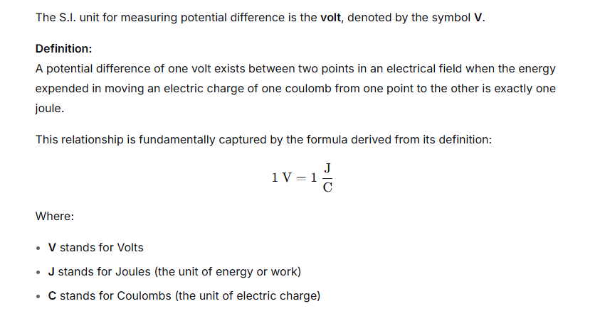
State and define the S.I. unit of potential difference.
Ans:
Question 6.
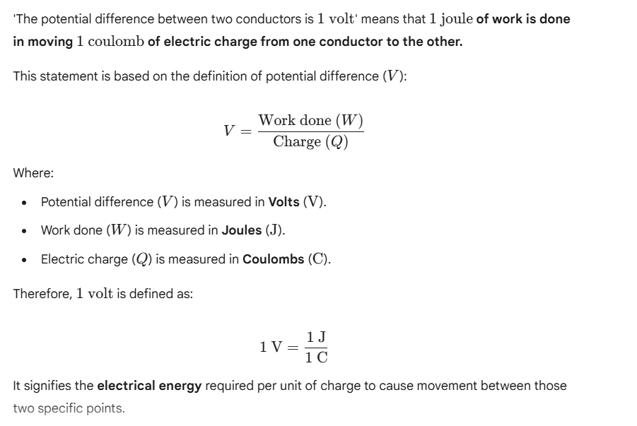
‘The potential difference between two conductors is 1 volt’. Explain the meaning of this statement.
Ans:
Question 7.
What do you understand by the term resistance?
Ans:
At its heart, resistance is the act of pushing back against something. It’s the “no” to a force, an idea, or a change. We see this concept play out in a few key areas:
1. In Our Daily Lives and Society
This is the most human form of resistance. It’s the opposition to something we disagree with or find oppressive. Think of:
- A citizen speaking out against an unjust law.
- A child refusing to eat their vegetables.
- The quiet determination to stick to a principle when everyone else is going along with the crowd.
In this sense, resistance is about maintaining autonomy and integrity. It’s a force that challenges the status quo and can be a powerful catalyst for personal or social change.
2. In Physics and Electronics
This is the most precise, scientific definition. Here, resistance is a fundamental property that quantifies how much a material opposes the flow of electric current. A simple analogy is water flowing through a pipe:
- Current is the flow of water itself.
- Voltage is the water pressure pushing the flow.
- Resistance is how narrow or rough the pipe is. A narrow, clogged pipe (high resistance) lets less water through, while a wide, smooth pipe (low resistance) allows for a strong flow.
In an electrical circuit, components called resistors are used intentionally to control the current, protect sensitive parts, or generate heat (like in a toaster). Without resistance, electronics as we know them would not function; currents would be uncontrollably high and destructive.
3. In Biology and Medicine
Here, resistance refers to the ability to withstand or fight off a threat.
- Disease Resistance: Your immune system provides resistance to infections. Some people have a natural resistance to certain illnesses.
- Antibiotic Resistance: This is a major global health concern. It occurs when bacteria evolve and no longer respond to the drugs designed to kill them, making infections much harder to treat.
The Common Thread
Whether it’s a person standing up for their rights, a wire limiting the flow of electricity, or a body fighting an infection, the core idea of resistance remains the same: it is a measure of opposition to a driving force. It is the fundamental friction that shapes outcomes, from the spark of social revolution to the simple operation of a light switch.
Question 8.
Explain why a metal wire when connected to a cell offers resistance to the flow of current.
Ans:
The Simple Idea: A Packed Hallway
Picture trying to sprint down a long, busy corridor where everyone is moving around. You can move forward, but you’re constantly bumped and blocked by the crowd. Your trip is much slower because of the obstacles.
In this picture:
- You are the electric current.
- The hallway is the wire.
- The crowd represents the metal’s atoms.
- Your slowed trip is the resistance.
The Real Science: A Look Inside the Wire
Inside a metal, atoms are locked in a vibrating grid. Their outer electrons are free to move randomly, like a chaotic swarm.
When you connect a battery, it creates a push—an electric field—that forces these free electrons to drift in one general direction. This flow is the current.
Resistance happens because the journey is rough. As electrons drift, they constantly smack into the vibrating atoms. Each collision steals energy, slowing the electron’s overall progress. The lost energy makes the atoms vibrate even more, which we feel as heat.
This explains key facts:
- Longer Wire = More Resistance: A longer path means more collisions.
- Thicker Wire = Less Resistance: A wider space gives electrons more room to flow.
- Hotter Wire = More Resistance: Heat makes atoms vibrate more wildly, creating more obstacles for electrons.
Question 9.
State and define the S.I. unit of resistance.
Ans:
The Unit of Resistance: The Ohm (Ω)
The standard international (SI) unit for quantifying this opposition is the ohm, symbolized by the Greek letter omega (Ω).
A Practical Definition
A material is said to have a resistance of one ohm when it permits a specific, balanced flow of electricity. More precisely:
One ohm exists when a steady electrical pressure of one volt results in an electric current of exactly one ampere flowing through the material.
This definition is a direct application of the relationship discovered by Georg Simon Ohm, known as Ohm’s Law. This law establishes a fundamental link between voltage (V, the “push”), current (I, the “flow”), and resistance (R, the “opposition”):
V = I × R
R = V / I
From this equation, the unit relationship becomes clear:
1 Ohm (Ω) = 1 Volt (V) / 1 Ampere (A)
Question 10.
State Ohm’s law.
Ans:
The fundamental relationship between voltage, current, and resistance within an electrical circuit is defined by Ohm’s law. This principle establishes that the steady flow of electrical current through a conductor is directly proportional to the potential difference applied across it, provided the physical conditions, such as temperature, remain unchanged.
Expressed mathematically, the law is captured by the formula:
V = I × R
Where:
- V represents Voltage, measured in volts (V). This is the electrical pressure that pushes the charges.
- I represents Current, measured in amperes (A). This is the flow rate of the electrical charges.
- R represents Resistance, measured in ohms (Ω). This is the opposition the conductor offers to the flow of current.
In practical terms, this means that increasing the electrical pressure (voltage) in a circuit with fixed resistance will cause a proportional increase in the flow of current. Conversely, for a given voltage, increasing the circuit’s resistance will result in a decrease in the current flow. This simple yet powerful relationship serves as the cornerstone for analyzing and understanding virtually all electrical and electronic systems.
Question 11.
How are the potential differences (V), current (l) and resistance (R) related?
Ans:
The relationship between electrical potential difference (V), current (I), and resistance (R) is one of the most fundamental concepts in electronics and physics. It is elegantly described by a principle known as Ohm’s Law.
Think of electricity flowing through a wire like water flowing through a pipe.
- Potential Difference (V – Volts) is the electrical “push” or pressure. It’s the force that motivates electrons to move. Using the water analogy, this is equivalent to the water pressure created by a pump or a height difference. Without pressure, water doesn’t flow; without voltage, current doesn’t flow.
- Current (I – Amperes) is the flow rate of the electrical charge itself. It measures how many electrons are passing a given point each second. In our water pipe, this is the volume of water flowing past a point per second—a wide, fast-moving river has a high current.
- Resistance (R – Ohms) is anything that opposes or restricts the flow of current. In a wire, it’s the natural friction the electrons encounter. In the water pipe, it’s a narrow section or a clog that slows the water down. A thin wire has high resistance; a thick wire has low resistance.
Ohm’s Law states that the potential difference (V) across a conductor is directly proportional to the current (I) flowing through it, provided the temperature and other physical conditions remain unchanged.
This relationship is captured by the famous formula:
V = I × R
What this means in practice:
- If Resistance is Constant: Increasing the voltage (the push) will cause a proportional increase in the current (the flow).
- If Voltage is Constant: Increasing the resistance (making it harder for current to flow) will cause the current to decrease. If you double the resistance, the current is cut in half. This is why a dimmer switch works; it adds resistance to the circuit, reducing the current to the light bulb.
- If Current is Constant: To maintain a specific current flow through a higher resistance, you must provide a higher voltage. This is akin to needing a more powerful pump to push water through a longer, narrower pipe at the same flow rate.
Question 12.
‘The resistance of a wire is 1 ohm’. Explain the meaning of this statement.
Ans:
The statement “The resistance of a wire is 1 ohm” is a quantitative description of how strongly the wire opposes the flow of electric current.
To understand this, imagine electricity as water flowing through a pipe. The wire is the pipe itself. A thin pipe filled with obstacles would make it difficult for water to flow—this pipe has high “resistance” to water flow. A wide, smooth pipe would allow water to flow easily, meaning it has low “resistance.”
In electrical terms, a 1-ohm resistance means that when a specific electrical “push” (known as voltage) is applied, a specific amount of electrical “flow” (known as current) will pass through the wire.
More precisely, if a voltage of 1 volt is applied across the two ends of this specific wire, it will result in an electric current of 1 ampere flowing through it. This direct, inversely proportional relationship between voltage and current is defined by Ohm’s Law (Resistance = Voltage / Current).
Therefore, labeling the wire as having 1 ohm of resistance instantly tells an engineer or physicist how this component will behave in an electrical circuit, allowing them to predict and control the current flow. It is a fundamental property of the wire, determined by its material, thickness, length, and temperature.
Question 13.
How is the current flowing in a conductor changed if the resistance of conductor is doubled keeping the potential difference across it the same?
Ans:
Understanding the Change in Current When Resistance Doubles
Imagine the flow of electricity through a wire is like water flowing through a pipe. The water pressure pushing the flow is similar to Voltage (V). The amount of water moving past a point each second is like the Current (I), which is the flow of electrical charge. Now, if the pipe has a kink or becomes narrower, it resists the flow of water. This narrowing is the direct equivalent of Resistance (R) in an electrical circuit.
These three concepts are locked together by a fundamental principle of electronics known as Ohm’s Law. This law provides a simple but powerful mathematical formula:
Voltage (V) = Current (I) × Resistance (R)
This relationship allows us to predict precisely what will happen when we alter a circuit.
The Scenario: Doubling the Resistance
Let’s set up a real-world situation. Suppose you have a simple circuit with a battery and one resistor.
- Initial Setup: The battery provides a fixed voltage—let’s say 10 Volts. The resistor in the circuit has a value we’ll call R. According to Ohm’s Law, a specific amount of current, which we’ll call I, will flow through it. Our governing equation is:
10 = I × R - Making the Change: Now, without changing the battery, you swap out the resistor for a new one that has twice the resistance. The new resistance is 2R. The voltage from the battery remains steady at 10 Volts.
- The New Condition: With the new, higher resistance in place, a different amount of current will flow. We will call this new current I_new. Ohm’s Law for this updated circuit now states:
10 = I_new × (2R)
Finding the Mathematical Relationship
Because the battery’s voltage is the same in both cases (10 Volts in our example), the left side of both equations is identical. This means the right sides must also be equal to each other.
We can therefore write:
I × R = I_new × (2R)
To find the new current (I_new), we can solve this equation. We can divide both sides by R (assuming it’s not zero) to simplify:
I = I_new × 2
Finally, rearranging this gives us the clear result:
I_new = I / 2
The Practical Outcome
The conclusion is straightforward and absolute: If you double the resistance in a circuit while keeping the voltage constant, the current is cut in half.
Question 14.
State three factors on which the resistance of a wire depends. Explain how the resistance depends on the factors stated by you.
Ans:
The electrical resistance of a wire is a measure of how strongly it opposes the flow of electric current. It depends primarily on the following three factors:
1. The Length of the Wire (L)
How it depends: The resistance of a wire is directly proportional to its length. This means that if the length of the wire is doubled, its resistance also doubles. Conversely, if the length is halved, the resistance is halved.
Explanation: Think of an electric current as people trying to walk through a long, crowded corridor. The longer the corridor, the more obstacles and collisions (interactions with the atoms of the wire) they will encounter along the way, making the journey more difficult. In a wire, electrons drifting through the material collide with the fixed ions in the metallic lattice. A longer wire provides a greater path length for these collisions to occur, resulting in a higher overall resistance.
2. The Cross-Sectional Area of the Wire (A)
How it depends: The resistance of a wire is inversely proportional to its cross-sectional area. This means that if the thickness (area) of the wire is doubled, its resistance is halved.
Explanation: Using the same analogy, imagine the cross-sectional area as the width of the corridor. A narrow corridor (small area) forces people to squeeze together, creating more friction and making it harder to pass. A wide corridor (large area) allows people to spread out and move freely. In a thicker wire, there is a greater “space” for the electrons to flow. This increased space provides more parallel pathways for the electrons, reducing the number of collisions per electron and thus lowering the overall resistance.
3. The Material of the Wire (Resistivity – ρ)
How it depends: The resistance is determined by a fundamental property of the material called resistivity (ρ). Different materials have different inherent resistivities. A material with a high resistivity will have a high resistance, and a material with a low resistivity will have a low resistance, all other factors being equal.
Explanation: This factor relates to the internal structure of the material itself. Returning to the corridor analogy, the material defines what the “floor” is made of. Trying to walk through a corridor with a sticky, tar-like floor (a high-resistivity material like nichrome) is much harder than walking through one with a smooth, polished floor (a low-resistivity material like copper or silver). At a microscopic level, materials with a higher resistivity have atomic structures that cause more frequent and disruptive collisions for the drifting electrons, impeding their flow more effectively.
These three factors are combined in the fundamental formula for resistance: R = ρL / A.
Question 15.
How is the resistance of a wire affected if its (a) length is doubled, (b) radius is doubled?
Ans:
The Foundation: What Governs a Wire’s Resistance?
Before looking at changes, it’s crucial to understand the core principle. A wire’s opposition to electric current, known as resistance, isn’t arbitrary. It is directly shaped by two physical factors: its length and its thickness, with the material’s innate character playing a defining role.
This relationship is perfectly expressed by the formula:
R = ρL / A
In this formula:
- R stands for the total electrical resistance.
- ρ (the Greek letter ‘rho’) is the material’s resistivity. This is a fixed value that measures how strongly the material naturally opposes electric current.
- L is the total length of the wire.
- A is the cross-sectional area of the wire (essentially, the measure of its thickness).
Now, let’s explore how altering the wire’s dimensions directly impacts its resistance.
(a) The Consequence of Doubling the Wire’s Length
Imagine electricity as a crowd of people trying to move through a long corridor. The longer the corridor, the more effort and time it takes to get to the end.
Applying this to our wire:
- We start with an original resistance: R₁ = ρL / A
- We then double the length, so the new length becomes 2L.
- The new resistance becomes: R₂ = ρ(2L) / A
This can be rearranged as R₂ = 2 × (ρL / A). Since the term (ρL / A) is our original resistance R₁, we find:
R₂ = 2 × R₁
Conclusion: When you double the length of a wire, you double its resistance. The electrons now have to travel twice the distance, encountering twice as many obstacles from the wire’s atomic structure.
(b) The More Dramatic Effect of Doubling the Wire’s Radius
Changing the thickness has a more powerful and sometimes less intuitive effect because it alters the cross-sectional area. For a round wire, the area A is calculated using the formula for a circle’s area, πr², where r is the radius.
- Our starting resistance is: R₁ = ρL / (πr²)
- We double the radius, so the new radius is 2r.
- Let’s calculate the new area: A₂ = π(2r)² = π × 4r² = 4πr²
Notice that doubling the radius does not just double the area; it quadruples it because the radius is squared in the area calculation.
Now, we plug this new, much larger area into the resistance formula:
- New Resistance: R₂ = ρL / A₂ = ρL / (4πr²)
Now, compare R₂ to our original R₁. The expression for R₂ is exactly one-quarter of the expression for R₁. We can state this as:
R₂ = (1/4) × R₁ or R₂ = R₁ / 4
Question 16.
State whether the resistance of filament of a bulb will decrease, remain unchanged or increase when it glows.
Ans:
We often think of a material’s resistance as a fixed number, but for a light bulb’s filament, it is anything but. The key to understanding why its resistance changes lies in what happens when you turn the light on.
A cold filament, like one in a bulb that has been off for hours, is a much more inviting path for electricity than we might assume. Its tungsten metal is coiled and ready, but at room temperature, the metal atoms are relatively calm. This orderliness allows electrons to flow through with less obstruction, resulting in a surprisingly low electrical resistance.
The moment you flip the switch, this changes dramatically. A surge of current rushes into the cool, low-resistance filament. This immense flow of electrons doesn’t just move through the tungsten; it violently jostles the atoms themselves, transferring energy into them as intense heat. In a fraction of a second, the filament’s temperature skyrockets from room temperature to well over 2000 degrees Celsius, making it white-hot.
At this extreme temperature, the atoms of the filament are vibrating with tremendous energy. Imagine trying to walk calmly through a quiet room versus trying to walk through the same room while a crowd is jumping and shoving wildly. The chaotic, intense vibrations of the heated atoms create a far more obstructed path for the flowing electrons. This atomic “traffic jam” is what we measure as a higher electrical resistance.
Therefore, the act of glowing is not just a side effect; it is the direct cause of the resistance increase. The brilliant white light we see is a visual indicator of the filament’s incredibly high operating temperature, a state where its resistance has multiplied many times over its resting, cold value.
Question 17.
1. Name the physical quantity of which the unit is volt
2. Name the physical quantity of which the unit is coulomb.
3. Name the physical quantity of which the unit is ohm
4. Name the physical quantity of which the unit is ampere
Ans:
- The physical quantity for which the unit is the volt is electrical potential difference (also known as voltage).
- The physical quantity for which the unit is the coulomb is electric charge.
- The physical quantity for which the unit is the ohm is electrical resistance.
- The physical quantity for which the unit is the ampere is electric current.
Exercise 9 (B)
Question 1.
Current in a circuit flows :
- In direction from high potential to low potential
- In direction from low potential to high potential
- In direction of flow of electrons
- In any direction.
Question 2.
The unit of potential difference is :
- ampere
- volt
- ohm
- coulomb
Question 3.
On increasing the resistance in a circuit, the current in it :
- Decreases
- Increases
- Remains unchanged
- Nothing can be said.
Exercise 9 (B)
Question 1.
In transferring 1.5 C charge through a wire, 9 J of work is needed. Find the potential difference across the wire.
Ans:
To find the potential difference, also known as voltage, we use the core principle that connects electrical energy, charge, and electric potential.
The foundational formula for this is:
Energy Transferred = Charge Moved × Potential Difference
This can be written as:
E = Q × V
Where:
- E stands for the electrical energy transferred, measured in joules (J).
- Q represents the amount of electric charge that is moved, measured in coulombs (C).
- V is the potential difference, which is measured in volts (V).
From the problem, we have the following data:
- The charge moved, Q, is 1.5 C.
- The energy transferred in moving this charge, E, is 9 J.
Our objective is to calculate V. We can rearrange the formula to isolate the voltage:
V = E / Q
Now, we substitute the known numerical values into this equation:
V = 9 J / 1.5 C
Performing this division gives the result:
V = 6 V
Question 2.
A cell of potential difference 12 V is connected to a bulb. The resistance of the filament of the bulb when it glows is 24Ω. Find the current drawn from the cell.
Ans:

Question 3.
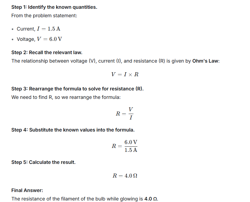
A bulb draws current 1.5 A at 6.0 V. Find the resistance of the filament of the bulb while glowing.
Ans:
Question 4.
A current 0.2 A flows in a wire of resistance 15Ω. Find the potential difference across the ends of the wire.
Ans:
The relationship between potential difference (V), current (I), and resistance (R) is defined by Ohm’s law.
Ohm’s law is stated as:
(V) = Current (I) × Resistance (R)
We are given:
- Current, I = 0.2 A
- Resistance, R = 15 Ω
Substituting the provided values into the formula:
V = 0.2 A × 15 Ω
Calculating the result:
V = 3 V
Therefore, the potential difference across the ends of the wire is 3 volts.
Exercise 9 (C)
Question 1.
What is meant by the efficient use of energy?
Ans:
Efficient use of energy means achieving a desired result (like lighting a room, heating water, or driving a car) while consuming the minimum possible amount of energy.1 Essentially, it’s about maximizing the output (useful work or service) relative to the energy input.
Here is a breakdown of the concept:
Key Concepts
- Minimizing Waste: Energy efficiency focuses on reducing the amount of wasted energy, which is energy that is converted into a non-useful form (like heat from a light bulb or sound from a poorly maintained machine).
- Technology and Behavior: Achieving efficiency involves both using advanced technologies (e.g., switching from incandescent bulbs to LED bulbs) and adopting better habits (e.g., turning off lights when leaving a room).
Analogy
Think of pouring water into a glass with a hole in the bottom.
- Inefficient Use: Using a leaky glass means you need to pour more water (more energy input) just to keep the glass half-full (desired result), wasting the rest.
- Efficient Use: Using a non-leaky glass (an efficient device) means you pour exactly the amount of water needed to keep the glass half-full, minimizing waste.
Question 2.
State two ways to save energy.
Ans:
Two Ways to Save Energy
1. Optimize Lighting: Switch to Energy-Efficient Bulbs
The simplest and most immediate way to save electricity is to replace incandescent bulbs with LED (Light Emitting Diode) bulbs.
- Action: Switch to LED bulbs.
- Why it Saves Energy: LED bulbs use up to 80% less energy than traditional incandescent bulbs and last significantly longer, reducing both energy consumption and replacement costs.
- Bonus: Always turn off lights when leaving a room to avoid wasting electricity on unused illumination.
2. Manage Appliance Power Consumption
Many appliances continue to draw small amounts of power even when they are turned off—this is often called phantom load or vampire power.
- Action: Unplug electronic devices and appliances when they are not in use, or use power strips and switch them off.
- Why it Saves Energy: Devices like phone chargers, televisions, and computers continue to consume energy in standby mode. By unplugging them or using a switched power strip, you completely cut off this wasted electricity, saving energy 24/7.
- Bonus: Use major appliances like washing machines and dishwashers only when you have full loads to maximize efficiency.
Question 3.
How does the proper insulation of home save energy?
Ans:
How Insulation Works to Save Energy
Insulation material, typically installed in attics, walls, floors, and crawlspaces, contains tiny air pockets. Air is a poor conductor of heat, and these pockets drastically slow down the movement of heat energy via the three mechanisms of heat transfer:
1. Reduces Heat Conduction
- Mechanism: Heat naturally flows from warmer areas to colder areas. In winter, this means heat moves from your warm living spaces to the cold exterior. In summer, heat moves from the hot exterior to the cool interior.
- Role of Insulation: Insulation materials (like fiberglass, cellulose, or foam) have a high thermal resistance .They are designed to be poor conductors, creating a major barrier that dramatically slows down the conductive flow of heat through solid materials like walls, ceilings, and frames.
2. Slows Down Heat Convection
- Mechanism: Convection involves heat transfer through the movement of fluids (like air). For example, warm air rises and cool air sinks, leading to cycles of heat loss or gain.
- Role of Insulation: Insulation prevents air movement within the structural cavities (like wall spaces). By trapping the air, it stops convection currents from forming and transporting heat across the envelope of the house.
3. Blocks Radiant Heat Transfer (Especially in Attics)
- Mechanism: Heat radiation moves as infrared waves.In the summer, the sun heats the roof, which then radiates heat down into the attic and the rooms below.
- Role of Insulation: Some insulation types, particularly radiant barriers, use reflective surfaces to reflect heat radiation away, preventing it from penetrating the living space. Even non-reflective insulation materials still absorb and slow down the transfer of radiant heat, keeping your home cooler.
Question 4.
Which of the following devices is most efficient for the lighting purpose?
LED, CFL, fluorescent tube light, Electric bulb.
Ans:
| Lighting Device | Efficiency Characteristic |
| Electric Bulb (Incandescent) | Least Efficient. Converts only about 5-10% of electricity into light; the rest is wasted as heat. |
| Fluorescent Tube Light | More efficient than incandescent bulbs, but generally less efficient than CFLs. |
| CFL (Compact Fluorescent Lamp) | Second Most Efficient. Uses about 75% less energy than an incandescent bulb to produce the same light. |
| LED (Light Emitting Diode) | Most Efficient. Can be up to 90% more efficient than a traditional incandescent bulb and up to 75% more efficient than CFLs. |
Question 5.
Give an example to explain that the use of modern eco-friendly technology is more efficient and less polluting.
Ans:
Brick Making: Old Problems, New Solutions
For generations, bricks in many regions were made in Bull’s Trench Kilns. These open trenches are filled with raw bricks and cheap fuels like coal mixed with waste. Once lit, they burn uncontrolled for over a week.
The cost is high. These kilns release thick, toxic smoke, harming local health and the environment. They are also incredibly wasteful, losing most of their heat to the air and producing many broken, unusable bricks.
A modern alternative, the Zig-Zag Kiln, changes everything. Its key innovation is an internal zig-zagging channel for hot air. This forces flames on a longer, twisting journey through the bricks.
This smarter design delivers two powerful wins. First, it slashes pollution by ensuring fuel burns more completely, cutting harmful smoke by up to 80%. Second, it captures heat that old kilns wasted, reducing fuel needs by nearly a third and creating a higher yield of quality bricks.
This proves that ecological progress isn’t a cost, but a smarter choice. It offers kiln owners better profits from lower fuel bills and a superior product, while giving communities the immediate gift of cleaner air.
Question 6.
Describe three ways for the efficient use of energy.
Ans:
Upgrade to Efficient Technology
- Swap older, inefficient devices and lighting with energy-certified models.
- Specifically, replace incandescent bulbs with LEDs, which consume up to 80% less power and have a longer lifespan.
- Select appliances with high energy ratings (like ENERGY STAR) to reduce electricity consumption for daily functions.
Improve Thermal Efficiency at Home
- Enhance insulation in walls, attics, and floors to minimize heat loss or gain, keeping indoor temperatures stable.
- Seal air leaks using weatherstripping around doors and windows to reduce the stress on heating and cooling systems (HVAC), which are major energy users.
Choose Sustainable Mobility
- Practice eco-driving by maintaining steady speeds and keeping tires properly inflated to maximize vehicle fuel economy.
- Whenever practical, choose walking, cycling, or public transit over driving solo to lower overall fuel consumption related to personal travel.
Question 7.
What social initiatives must be taken for the sensitive use of energy?
Ans:
Social initiatives for the sensitive use of energy focus on changing behavior and promoting sustainable practices across communities. Here are key initiatives:
Community-Level Initiatives
- Energy Audit Programs: Organize free or subsidized energy audits for households and small businesses to identify specific areas of waste and recommend cost-effective efficiency upgrades (e.g., better insulation, sealing air leaks).
- Neighborhood Challenges & Incentives: Launch local competitions or challenge programs (e.g., “The Lowest Energy Bill of the Month”) with small rewards or public recognition to motivate residents to reduce consumption.
- Appliance Exchange Programs: Offer incentives or collection services to help people replace old, inefficient appliances (like refrigerators and air conditioners) with new, ENERGY STAR-rated models.
Education and Awareness
- Public Awareness Campaigns: Run campaigns across local media and social platforms focusing on simple, high-impact actions, such as “switch off, unplug, save.”
- School Curricula Integration: Incorporate energy literacy and climate change education into primary and secondary school programs to establish lifelong sensitive energy habits.
- Workshops and Training: Host free workshops on topics like solar panel installation, rainwater harvesting, and optimizing home heating/cooling systems.
Policy and Infrastructure
- Smart Grid Adoption Education: Inform the public about the benefits of smart meters and flexible energy use (shifting usage to off-peak hours) to help balance the grid and reduce reliance on peak power generation.
- Promoting Public and Active Transport: Advocate for and fund better public transportation, as well as safe biking and walking infrastructure, to reduce dependency on personal vehicles.
- Collective Investment Schemes: Establish community funds or co-ops that allow residents to collectively invest in local renewable energy projects, like a neighborhood solar farm, giving them a direct stake in clean energy production.
Exercise 9 (C)
Question 1.
The most non-polluting and efficient lighting device is :
- CFL
- LED
- Fluorescent light
- Electric bulb
Question 2.
IEA is the short form of :
- Indian Energy Association
- Indian Eco Academy
- International Energy Agency
- International Eco Academy
